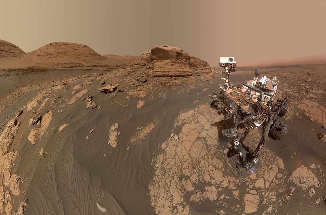
In addition to model development, the Mars Climate Modeling Center (MCMC) conducts cutting-edge scientific research on the past and present atmosphere and climate of Mars.
The Mars Climate Modeling Center (MCMC) conducts atmospheric and climate science research using the NASA Ames Mars Global Climate Models (MGCMs), advancing our understanding of Mars’ climate today, in its ancient past, and as a target for future exploration.
Mars’ climate is governed by three interacting cycles — dust, water, and carbon dioxide (CO₂) — that vary across seasons and from year to year. MCMC scientists use the MGCMs to study these cycles and the processes that drive them, including:
Dust storms and dust transport – Investigating the mechanisms that lift, transport, and remove dust in the Martian atmosphere, including the onset and evolution of regional and global-scale dust storms.
Water and CO₂ cycles – Studying the seasonal exchange of water and CO₂ between the atmosphere, polar caps, and surface, and the clouds that form as a result.
Atmospheric dynamics – Examining circulation patterns, wave-mean flow interactions, and the extension of the MGCM into the middle atmosphere to better connect the lower and upper atmosphere.
Ancient Mars and habitability – Reconstructing past climate states, including the role of asteroid and comet impacts, to assess when and where conditions may have supported liquid water and habitability.
Mission support – Applying model results to landing site selection and characterization, atmospheric entry planning, and interpretation of data from current and past Mars missions.
This research is carried out by a team of civil servant and contractor scientists, postdoctoral researchers, and students, often in collaboration with universities and other NASA centers. You can read more about individual MCMC team members and their science on the Group Members page. A full list of MCMC research papers, conference presentations, and technical reports is available on the Publications page.
B.2 Heliophysics Foundational Research (HFR) solicits investigations that advance the fundamental physical understanding of the Sun-Heliosphere-Planetary system. The emphasis of HFR is on uncovering and characterizing the underlying drivers, couplings, and governing processes that shape heliophysical phenomena across spatial and temporal scales, from the solar interior to planetary environments.
ROSES-2025 Amendment 66 announces that the Step-2 due date for B.2 HFR, which was previously TBD, is now September 25, 2026. Step-2 proposals can only be submitted by those who submitted a Step-1 proposal and were invited to submit a Step-2.
Also, the requirements for Biographical Sketches and Current and Pending Support have been updated, see the table of Requirements for Expertise and Resources Not Anonymized (E&R) Document on page 11 in Section 3.2. New text is in bold.
Additional Directions: – See full text of the RFI here – Provide the following information by 11:59 p.m. Eastern time on TBD XX, 2026. – Character limit for the responses to the topics is 3,000 or ~500 words
This field is for validation purposes and should be left unchanged.
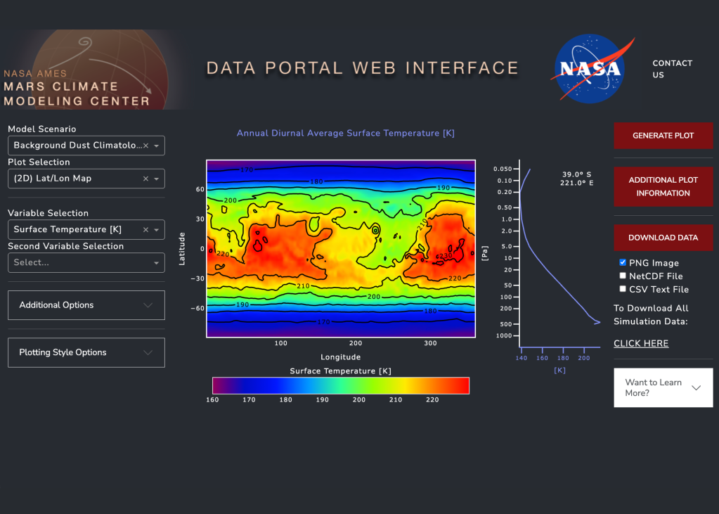
The Mars Climate Modeling Center (MCMC) presents the webserver, a website for interactive plotting and downloading Mars Global Climate Model (MGCM) output.
The model visualization tool offers the most accessible introduction to Mars Global Climate Model (MGCM) data. It is an online dashboard that allows users to interactively plot, explore, and download model output stored on the NAS Data Portal (see the MGCM Output tab for more information).
GCM analysis tools
MGCM Webserver
You can explore, plot, and download the MGCM output through our user-friendly web interface.
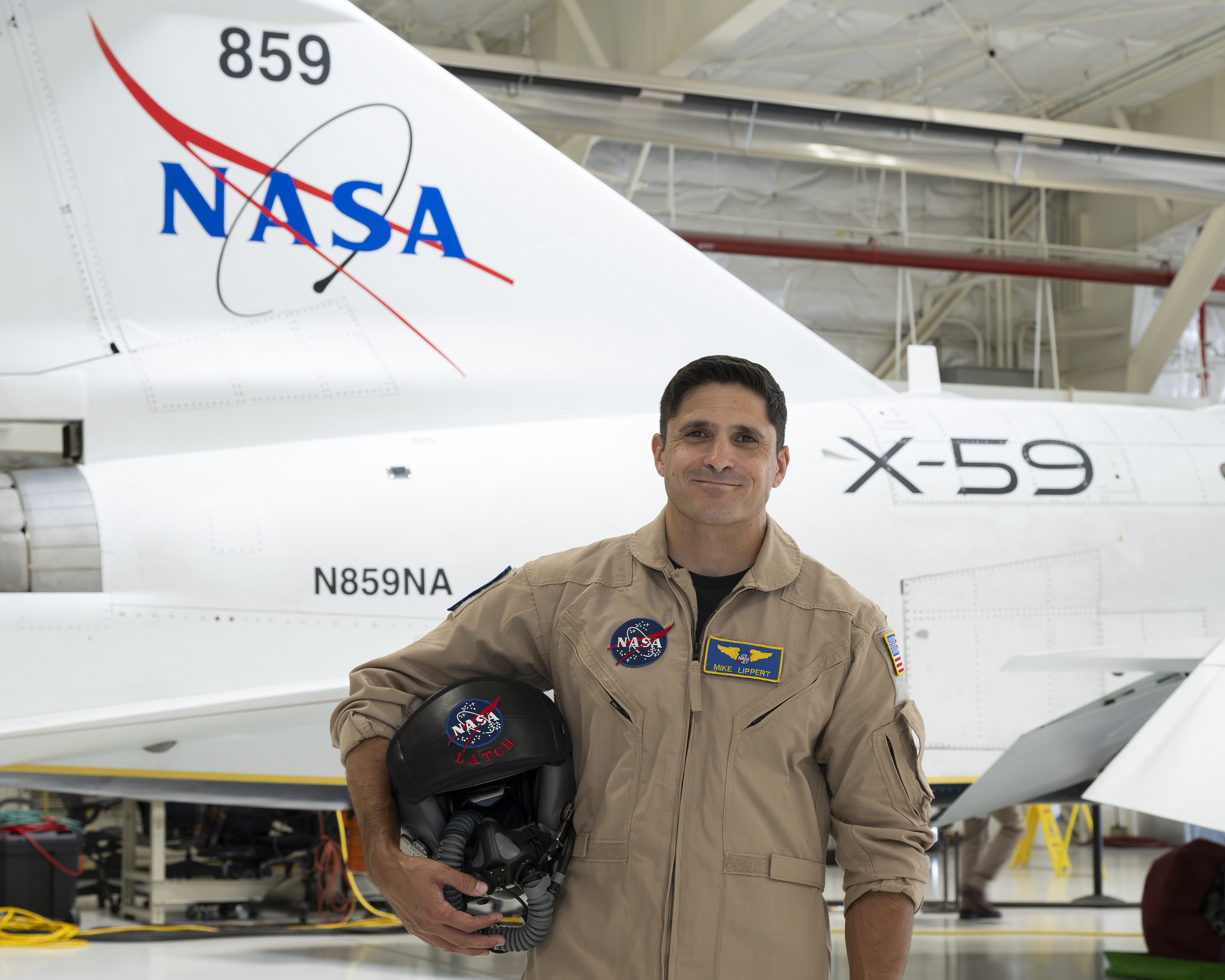
NASA’s X-59 test pilot Mike Lippert stands in front of the agency’s X-59 quiet supersonic research aircraft at NASA’s Armstrong Flight Research Center in Edwards, California, on Wednesday, June 24, 2026.
NASA/Carla Escamilla
NASA added a new X-59 test pilot to support the agency’s Quesst mission: Mike Lippert, a research test pilot based at NASA’s Armstrong Flight Research Center in Edwards, California.
“This fulfills a lifelong dream of conducting airborne research and experimental flight test for NASA in the high desert — contributing to humankind’s understanding of the science of flight and the nature of the world around us,” Lippert said.
Lippert will fly the X-59, along with the F-15 and F-18 support aircraft to monitor the quiet supersonic X-plane when it’s in the air. He joins Nils Larson and Jim “Clue” Less, who have been flying the X-59 since its first flight in October 2025.
A South Carolina native, Lippert served 20 years with the U.S. Marine Corps before retiring last year as a lieutenant colonel. Like his fellow test pilots, he boasts an impressive flight resume, including logging more than 2,600 hours of flight time in 60 different types of aircraft.
Lippert said he finds test pilot work especially rewarding.
“For me, the joy of taking part in experimental flight test and airborne research is the experience of discovery and learning something new every day,” he said. “It is incredibly rewarding to be part of a team solving complex problems and venturing into the unknown, together.”
Lippert spent the majority of his career flying the AV-8B Harrier operationally and serving as a test pilot in the F-35 program. He is also an aerospace engineer, earning a bachelor’s degree from the United States Naval Academy in Annapolis, Maryland, and a Master of Science in flight test engineering from the U.S. Air Force Test Pilot School at Edwards Air Force Base in California. Additionally, he earned a Master of Science in systems engineering from the Naval Postgraduate School in Monterey, California.
Lippert is currently pursuing a doctoral degree in aerospace engineering at the University of Alabama Graduate School in Tuscaloosa, where his research focuses on high-speed gas dynamics, including supersonic and hypersonic fluid mechanics — complementing his work on the Quesst mission.
Lippert is busy preparing for his role at NASA by flying training flights on support aircraft and spending time in the X-59 simulator. He is expected to begin flying the X-59 later this summer.
Michael T. Lippert is a research test pilot at NASA’s Armstrong Flight Research Center in Edwards, California. He is assigned to fly the agency’s X-59 quiet supersonic research aircraft, along with the F-15 and F/A-18 support aircraft, and to support NASA’s advanced air mobility research projects.
Experience
Prior to joining NASA in 2026, Lippert served 20 years in the U.S. Marine Corps before retiring as a lieutenant colonel in 2025. He was a flight instructor at Naval Air Station Kingsville in Texas, where he trained U.S. Navy and Marine Corps officers in tactical jet aircraft. He has more than 2,600 hours of flight experience in 60 types of aircraft.
The bulk of his career was spent flying the AV-8B Harrier operationally and serving as a test pilot in the F-35 program. During his last two assignments, he served as the chief test pilot of Marine Operational Test and Evaluation Squadron One at Marine Corps Air Station Yuma in Arizona, and as the government flight test director of the F-35 Integrated Test Force at Naval Air Station Patuxent River in Maryland.
Education
Lippert earned a bachelor’s degree in aerospace engineering in 2005 from the United States Naval Academy in Annapolis, Maryland, and a Master of Science in flight test engineering in 2016 from the U.S. Air Force Test Pilot School at Edwards Air Force Base, California. Lippert also earned a Master of Science in systems engineering in 2019 from the Naval Postgraduate School in Monterey, California. He is currently pursuing a doctoral degree in aerospace engineering at the University of Alabama Graduate School in Tuscaloosa, Alabama. His research focuses on high-speed gas dynamics, including supersonic and hypersonic fluid mechanics.
Awards
Lippert is an associate fellow of the Society of Experimental Test Pilots and a member of the American Institute of Aeronautics and Astronautics. He was part of the multi-agency team that received the Collier Trophy in 2018 for the Automatic Ground Collision Avoidance System. He also contributed to the team that received a Silver Medal from the Royal Aeronautical Society for F-35 testing aboard HMS Queen Elizabeth, a British Royal Navy aircraft carrier.
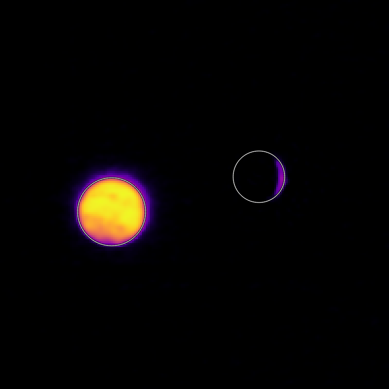
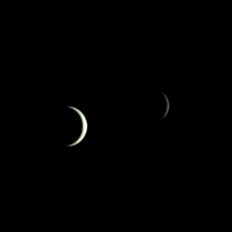
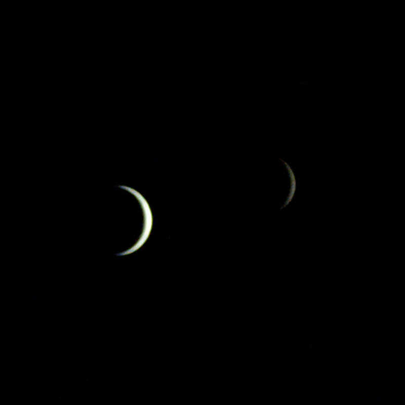
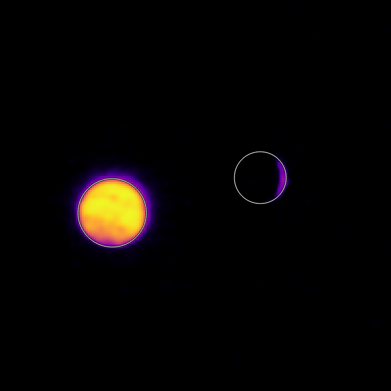
On July 3, one of NASA’s two Mars-destined ESCAPADE (Escape and Plasma Acceleration and Dynamics Explorers) spacecraft captured photos of Earth and the Moon in visible and thermal infrared light. At the time, the spacecraft was 363,250 miles (584,600 kilometers) from Earth and 115,600 miles (186,100 kilometers) from the Moon, making the Moon appear relatively large.
Taken with the Sun only partly illuminating Earth and the Moon, the visible light image shows the two bodies as crescents, with only around 8% of each face sunlit. Yet in the thermal infrared image, the shadowed hemisphere of Earth is illuminated by its own heat from both the atmosphere and surface, glowing at minus 10 to minus 44 degrees Fahrenheit (250 to 280 kelvins). Without the insulating blankets of oceans and atmospheres, the Moon’s far side remains at a much cooler minus 280 degrees Fahrenheit (100 kelvins).
visible light
thermal infrared light
Caption: In these images from NASA’s ESCAPADE mission, Earth (left) and Moon (right) can be seen. The image to the left of the slider shows visible light reflected by the Sun while the infrared image to the right shows the bodies’ emitted energy. White rings have been added in the thermal image to show the actual size of Earth and the Moon. Credit: NASA/UCB-SSL/NAU-Radiant/Lucint
NASA/UCB-SSL/NAU-Radiant/Lucint
In these images from NASA’s ESCAPADE mission, Earth (left) and Moon (right) can be seen. The image to the left of the slider shows visible light reflected by the Sun while the infrared image to the right shows the bodies’ emitted energy. White rings have been added in the thermal image to show the actual size of Earth and the Moon.
NASA/UCB-SSL/NAU-Radiant/Lucint
visible light
thermal infrared light
ESCAPADE Photos of Earth and Moon
July 3, 2026
In these images from NASA’s ESCAPADE mission, Earth (left) and Moon (right) can be seen. The image to the left of the slider shows visible light reflected by the Sun while the infrared image to the right shows the bodies’ emitted energy. White rings have been added in the thermal image to show the actual size of Earth and the Moon. Credit: NASA/UCB-SSL/NAU-Radiant/Lucint
The ESCAPADE mission used its Visible and Infrared Observation System cameras, provided by Northern Arizona University in Flagstaff, to capture the images, which are more than just road trip photo album snaps.
“We are thrilled that ESCAPADE was able to accommodate these excellent space-qualified cameras which will search for visible Martian aurora and investigate thermal properties of the Martian surface and atmosphere,” said Rob Lillis, the mission’s principal investigator at the University of California, Berkeley. “Since Earth and the Moon are well-known targets, imaging them provides an important calibration check for ESCAPADE’s cameras.”
The ESCAPADE spacecraft, which were built by Rocket Lab, are currently in a “loiter” orbit around Lagrange point 2, a location in space about a million miles from Earth. In November 2026, the spacecraft will fly by Earth to use the planet’s gravity to slingshot their way to Mars. When the spacecraft arrive in September 2027, they will study how a million-mile-per-hour stream of material flowing from the Sun, known as solar wind, interacts with the Martian environment and how that drives atmospheric loss at the Red Planet.
The ESCAPADE mission is funded by NASA’s Heliophysics Division and is part of the NASA Small Innovative Missions for Planetary Exploration program. The UC Berkeley’s Space Sciences Laboratory leads the mission with key partners Rocket Lab; NASA’s Goddard Space Flight Center in Greenbelt, Maryland; Embry-Riddle Aeronautical University; Advanced Space; and Blue Origin.
By Mara Johnson-Groh NASA’s Goddard Space Flight Center, Greenbelt, Md.
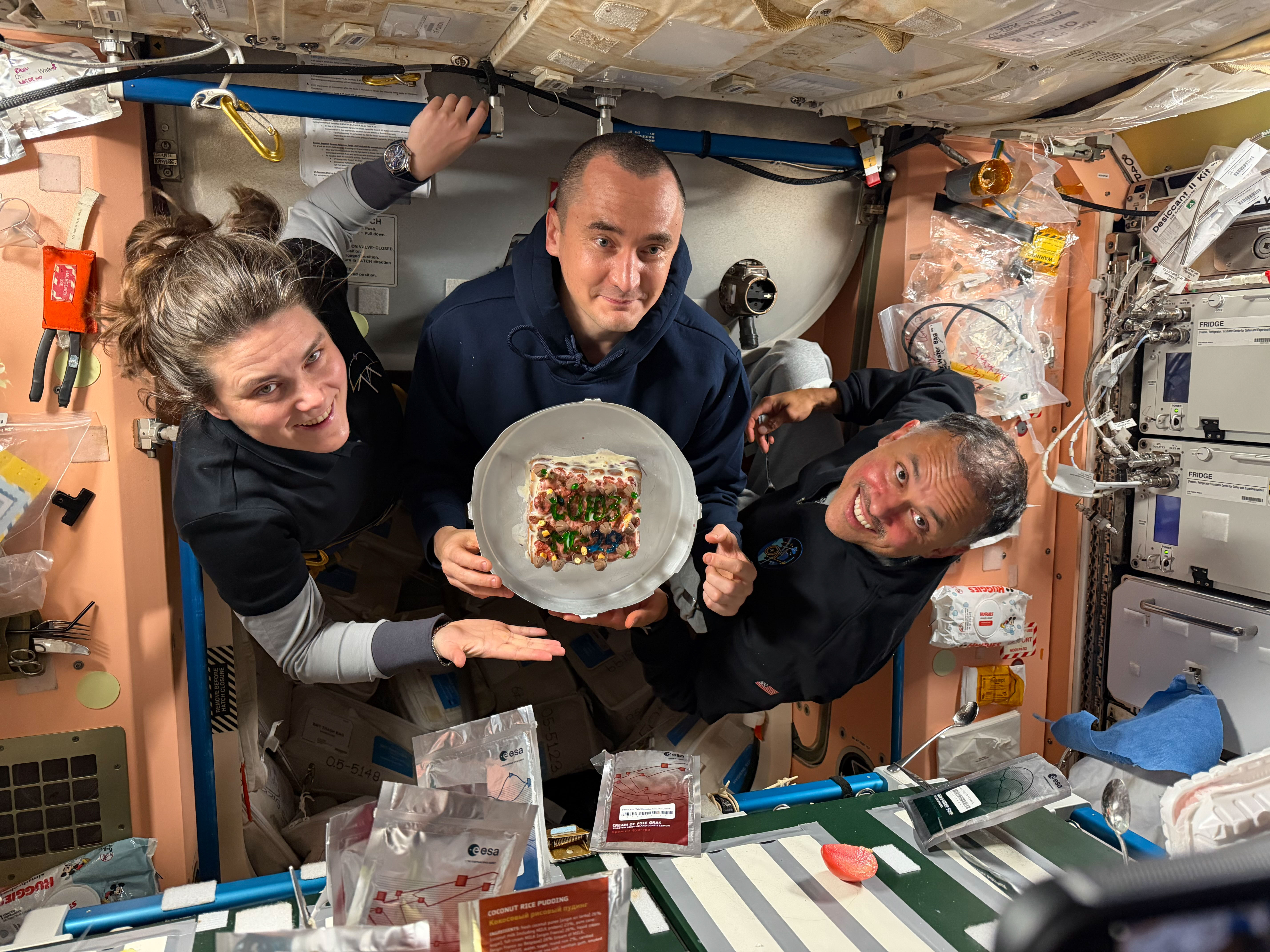
From left, Expedition 74 flight engineers Anna Kikina and Pyotr Dubrov of Roscosmos, and Anil Menon of NASA pose for a July 18, 2026, photo while holding a cake celebrating their recent arrival aboard the International Space Station. The trio arrived at the space station on July 14, 2026, after launching from the Baikonur Cosmodrome in Kazakhstan earlier the same day.
Kikina, Dubrov, and Menon are in the second week of their planned eight-and-a-half-month mission. They are using their new skills to conduct space research while still familiarizing themselves with living and working in space.
NASA Announces New Spacecraft Technology Demonstration Mission at Moon
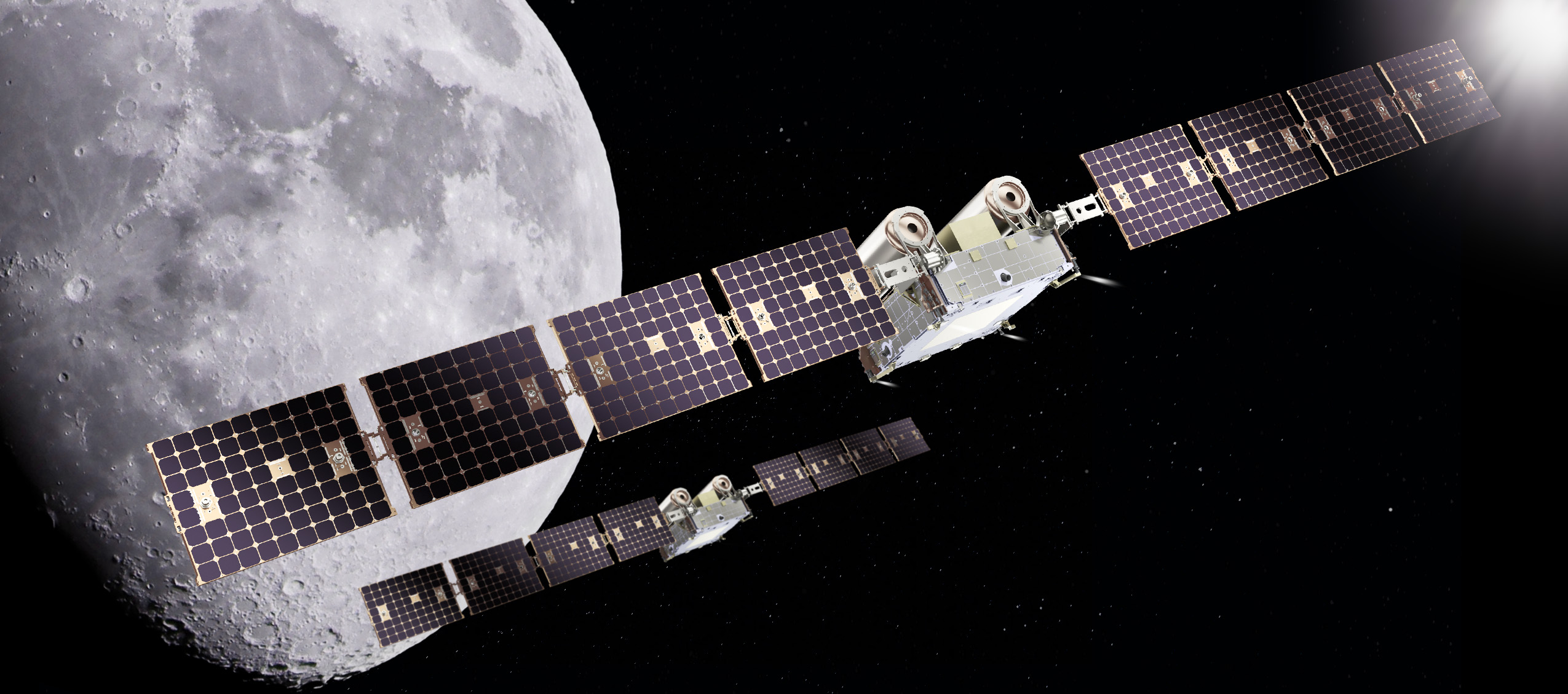
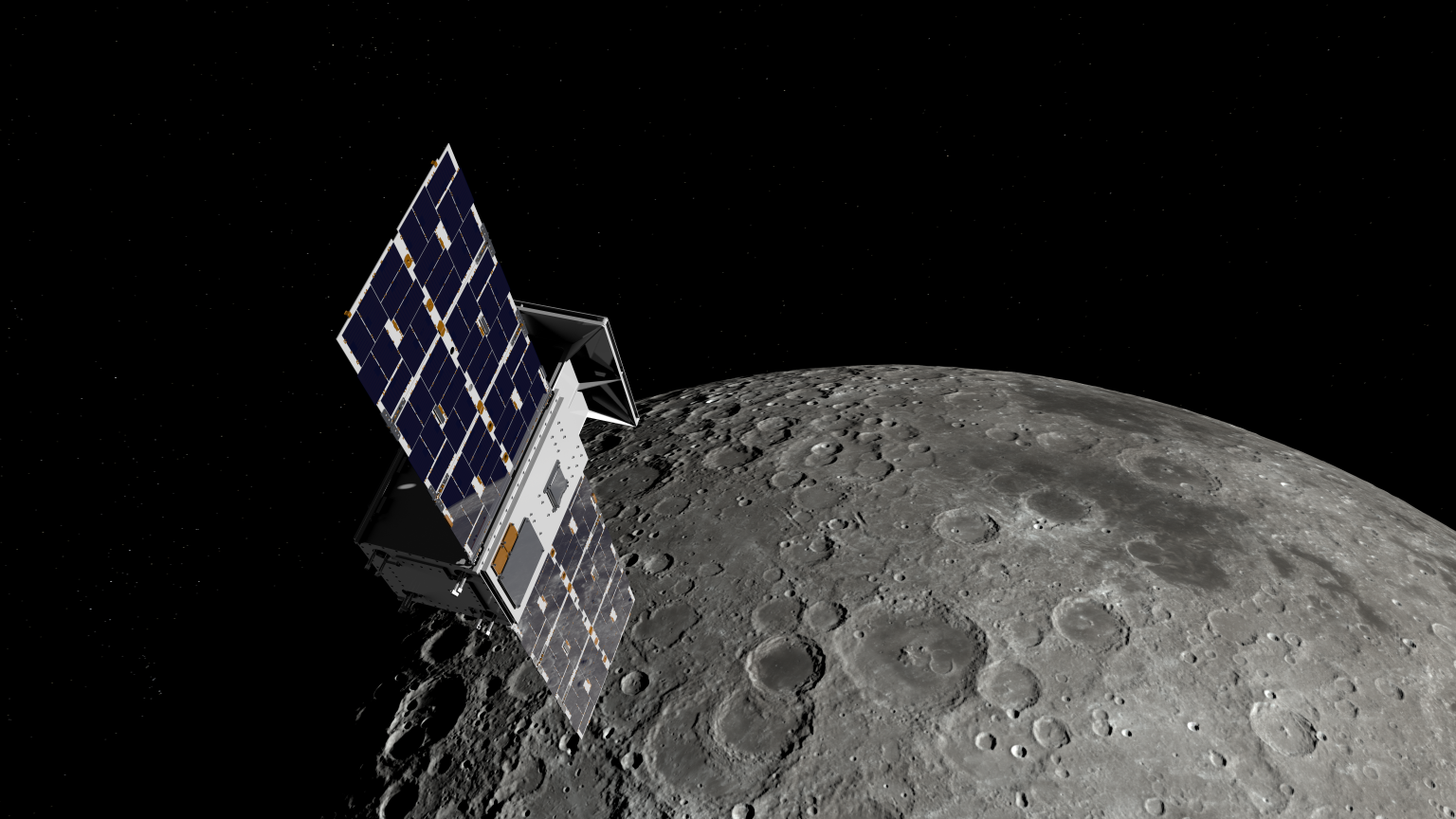
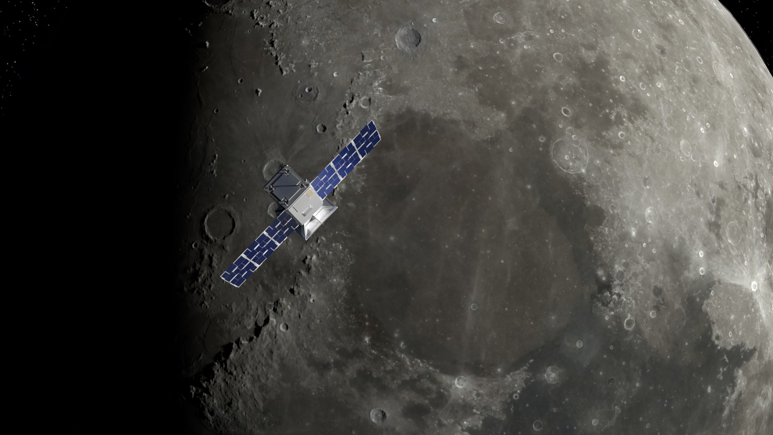
An artist’s rendering of NASA’s CAPSTONE 02 spacecraft in lunar orbit. The mission features two identical small spacecraft that will further mature technologies to support Artemis, Moon Base, and deep space exploration.
Terran Orbital
NASA is working with industry to advance the next phase of cislunar infrastructure for the agency’s Artemis program and Moon Base, including orbital assets and demonstrations. Under a contract awarded to Advanced Space, the agency’s CAPSTONE 02 mission will demonstrate rendezvous and proximity operations, autonomous navigation, and cislunar communication capabilities while continuing to characterize the radiation environment at the Moon.
The CAPSTONE 02 mission, targeted for launch in 2027, will use two small spacecraft in lunar orbit to facilitate these demonstrations to support future NASA lunar and deep space missions.
NASA’s original CAPSTONE demonstration, short for Cislunar Autonomous Positioning System Technology Operations and Navigation Experiment, became the first U.S. commercial mission to the Moon and the first spacecraft to operate in a near rectilinear halo orbit around the Moon. This is a nearly stable orbit, thanks to the interactive pull of gravity from both the Earth and the Moon.
The mission successfully validated communications, networking, and autonomous navigation capabilities while gathering operational experience in cislunar space. The second CAPSTONE mission expands upon these accomplishments by transitioning from orbit validation to demonstrations that will inform future lunar exploration and infrastructure development.
Achieving our most ambitious space exploration goals requires iterative, risk-tolerant demonstrations in partnership with industry. Technology development through flight testing is how we convert hard problems into the lasting capabilities needed for a permanent presence at the Moon.
Christopher Baker
Lead of the In‑Space Infrastructure portfolio within the Research and Technology Mission Directorate at NASA Headquarters in Washington, DC.
NASA’s CAPSTONE 02 mission will demonstrate advanced relative navigation technologies for rendezvous and proximity operations in cislunar space. These techniques are more sophisticated than those used in low Earth orbit and are designed to support NASA astronauts as they dock with Moon landers in cislunar orbit, enabling safe crew transfers to and from the lunar surface.
The demonstration will fly two identical spacecraft of approximately 400 kilograms (882 pounds) from Terran Orbital Systems, Inc. Mission operators will conduct a series of rendezvous and proximity operations and loitering – or formation flying – techniques in lunar orbit with each spacecraft to better understand the trajectories of the spacecraft under the simultaneous influence of Earth and Moon gravities, otherwise known as three-body orbits.
The CAPSTONE 02 mission will use ground tracking measurements, optical sensors, and celestial bodies to help one spacecraft locate and rendezvous with another. The mission will apply navigation strategies similar to those planned for Orion’s approach to a lunar lander in deep space, helping NASA build confidence in these techniques for future exploration.
Each CAPSTONE 02 spacecraft will have the ability to switch between ‘chaser’ and ‘target’ roles, testing a broad range of operational scenarios under a variety of environmental conditions in cislunar space. Transporting crew to the lunar surface from cislunar orbit depends on knowing how well navigation systems will perform during these operations. Since these conditions can’t be fully recreated on Earth, they must be tested in space.
The CAPSTONE 02 mission also will serve as an operational testbed, enabling testing of three NASA-developed navigation software suites. Each software application will collect data during CAPSTONE 02’s low energy transfer trajectory, which will take it from the Earth to beyond the Moon before settling into a lunar orbit. The spacecraft will carry an optical imaging payload from Lawrence Livermore National Laboratory to support the navigation demonstration as well as capture imagery of the Moon. In addition, the mission will further mature the Cislunar Autonomous Positioning System navigation software that was first demonstrated on CAPSTONE as a method of determining spacecraft position relative to other spacecraft without relying on Earth-based tracking.
The suite of technologies on CAPSTONE 02 are designed to automate routine navigation tasks, reduce reliance on traditional space-to-ground data, and enable new mission concepts that may be derived from increased inter-satellite coordination. Additionally, the CAPSTONE 02 spacecraft are designed for cost-effective, rapid deployment, demonstrating a scalable and repeatable mission model.
“This mission represents an important step in the maturation of cislunar capabilities,” said Sean Fuller, Moon Base CAPSTONE manager. “By expanding on the lessons learned from CAPSTONE to demonstrate increasingly sophisticated operational concepts, CAPSTONE 02 lays the foundation for lunar infrastructure and commercial services that support Artemis, Moon Base, and future missions to deep space.”
The CAPSTONE 02 mission is funded by NASA’s Human Spaceflight Mission Directorate with support from the Research and Technology Mission Directorate. The mission is managed by Small Spacecraft & Distributed Systems, based at NASA’s Ames Research Center in California’s Silicon Valley, within the Research and Technology Mission Directorate. NASA used a Small Business Innovation Research Phase III contract to fund the mission.
To learn more about NASA’s CAPSTONE mission, visit:
An image shows the B-1 and B-2 test stands at NASA’s Stennis Space Center near Bay St. Louis, Mississippi, on July 7, 2026. The test stand features dual, vertical firing positions built in the 1960s to test Saturn V rocket stages that carried humans to the Moon during the Apollo Program. The B-1 position, right, is equipped for single engine tests, while the B-2 position is designed to test full rocket stages. NASA announced an agreement with Blue Origin on July 24, 2026, to use the B-2 test stand for engine testing to advance rocket development for future missions to the Moon under the Artemis program.
Credit: NASA/Danny Nowlin
NASA and Blue Origin announced Friday they recently agreed to conduct second stage hot fire testing for the company’s New Glenn rocket on the B-2 test stand at the agency’s Stennis Space Center near Bay St. Louis, Mississippi.
The annex to a reimbursable Space Act Agreement signed earlier this month highlights NASA’s commitment to working alongside commercial partners toward Artemis missions in 2027 and beyond.
“Stennis continues to be a hub for the commercial space industry,” said Sen. Roger Wicker. “Mississippi warmly welcomes Blue Origin’s return to the coast and to our legendary rocket testing facilities.”
“The success of Artemis II has roots at NASA Stennis, and I’m excited about the prospect of Blue Origin establishing a rigorous test program in Mississippi as part of future American crewed missions to the Moon and beyond. I hope its use of B-2 test stand becomes a long-term arrangement that broadens our state’s contribution to space exploration. I will certainly do what I can to make that a reality,” said Sen. Cindy Hyde-Smith.
“Mississippi continues to play a vital role in America’s space program, and this agreement between NASA and Blue Origin is another major win for Stennis Space Center. The world-class capabilities at the B-2 test stand will help advance the next generation of rocket propulsion while supporting high-skilled jobs and strengthening our nation’s leadership in space exploration. I look forward to seeing the innovation that comes from this partnership,” said Rep. Mike Ezell.
Testing, targeted to begin this fall, directly supports NASA’s work to achieve the national goal of landing American astronauts on the surface of the Moon and building a Moon Base near the lunar South Pole. These efforts aim to strengthen American leadership in space, unlock scientific discovery, drive innovation with industry, and prepare for human missions to Mars.
“Winning the new space race means moving faster and working alongside a strong commercial industry. Supporting Blue Origin at NASA’s Stennis Space Center puts world-class American infrastructure to work advancing the capabilities needed to return astronauts to the Moon, establish a sustained lunar presence, and prepare for Mars. Partnerships like this strengthen our industrial base and help ensure the United States remains the world’s leader in space,” said NASA Administrator Jared Isaacman.
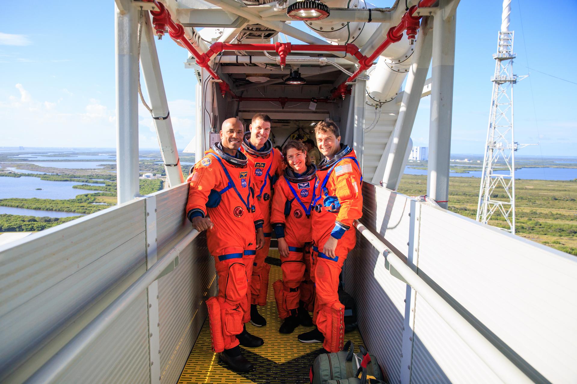
Building on the successful Artemis II flight from April, Artemis III is a highly choreographed, multi-launch campaign that will require four astronauts to test rendezvous and docking capabilities of NASA’s Orion spacecraft with commercial human landing systems from Blue Origin and SpaceX in low Earth orbit.
In addition, Blue Origin’s New Glenn will be used to launch missions that will land on the Moon.
“We are proud to partner with NASA and build on our shared commitment to returning America to the Moon and our broader mission to build a road to space for the benefit of Earth,” said Blue Origin CEO Dave Limp. “Stennis helped take Americans to the Moon, and through this partnership, it will help take us back.”
In May, NASA announced the first three Moon Base missions to begin building sustained operations, including an award to Blue Origin to launch a robotic mission this fall. The company’s Blue Moon Mark 1 Endurance lander will deliver NASA payloads to the lunar South Pole’s Shackleton Connecting Ridge, demonstrating capabilities that reduce risk for astronauts to land on the Moon during Artemis IV and V in 2028.
To support upcoming testing at Stennis, NASA will provide the engineers, equipment, and building services needed to design, build, and install parts that will prepare the B-2 for second stage testing of the rocket named in honor of the late NASA astronaut John Glenn, the first American to orbit Earth. The rocket’s second stage is powered by two BE‑3 engines that use liquid oxygen and liquid hydrogen propellants, with each engine generating 200,000 pounds of thrust in vacuum.
In addition to providing hands‑on technical support, NASA also will assist Blue Origin’s test operations by providing dedicated workspace and sharing agency expertise and lessons learned from propulsion testing conducted at the test stand.
Blue Origin will work toward second stage rocket testing on a stand with a history of testing rocket stages for Moon missions dating back to the 1960s. The agency constructed the stand to test the Saturn V rocket stages that carried humans to the Moon during the Apollo Program. More recently, NASA conducted a Green Run test series of the SLS core stage on the stand before the Artemis I test flight.
For more information about NASA’s Artemis program, visit:
NASA Pushes New Wing Design to Find Structural Limits
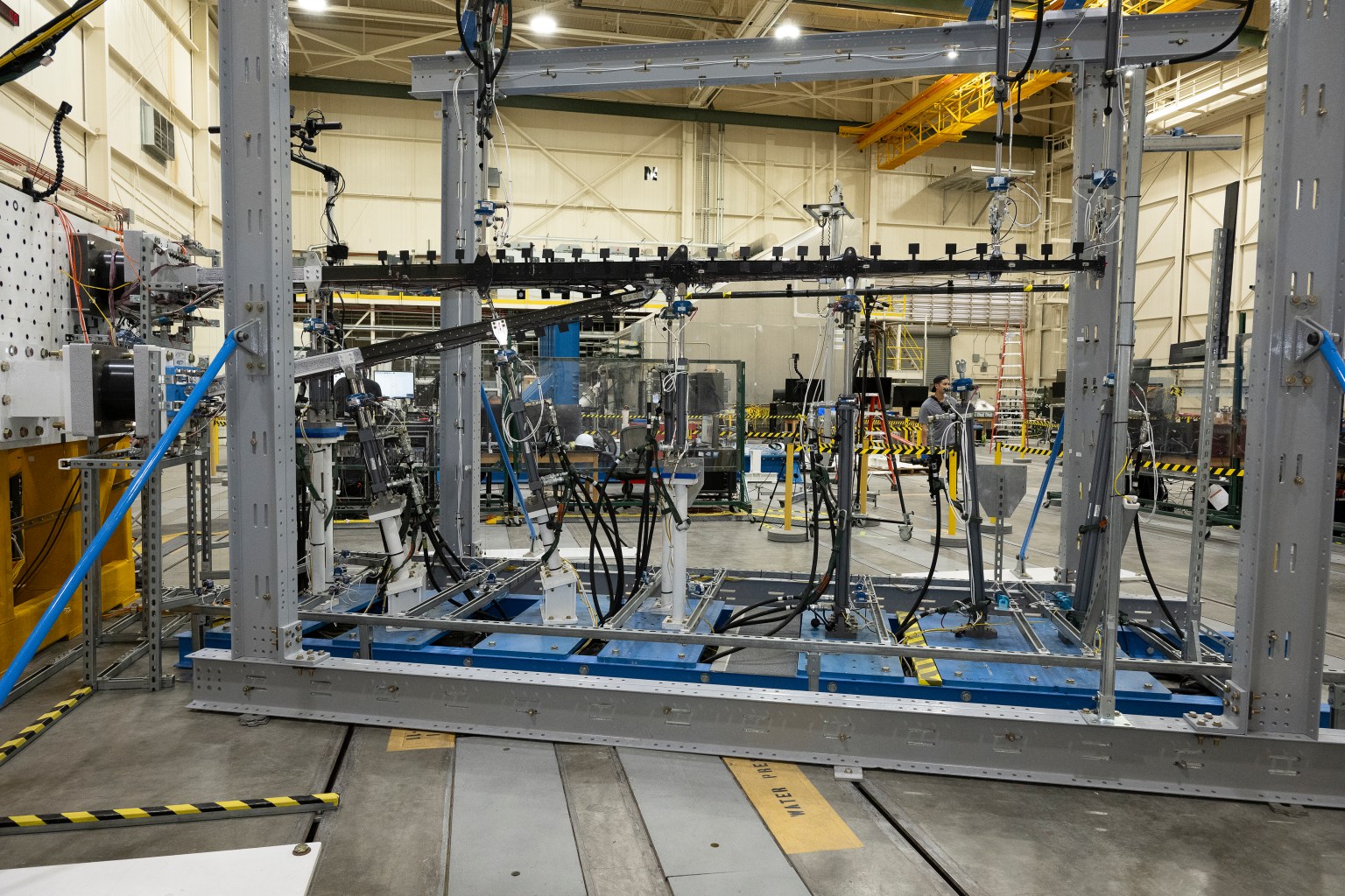
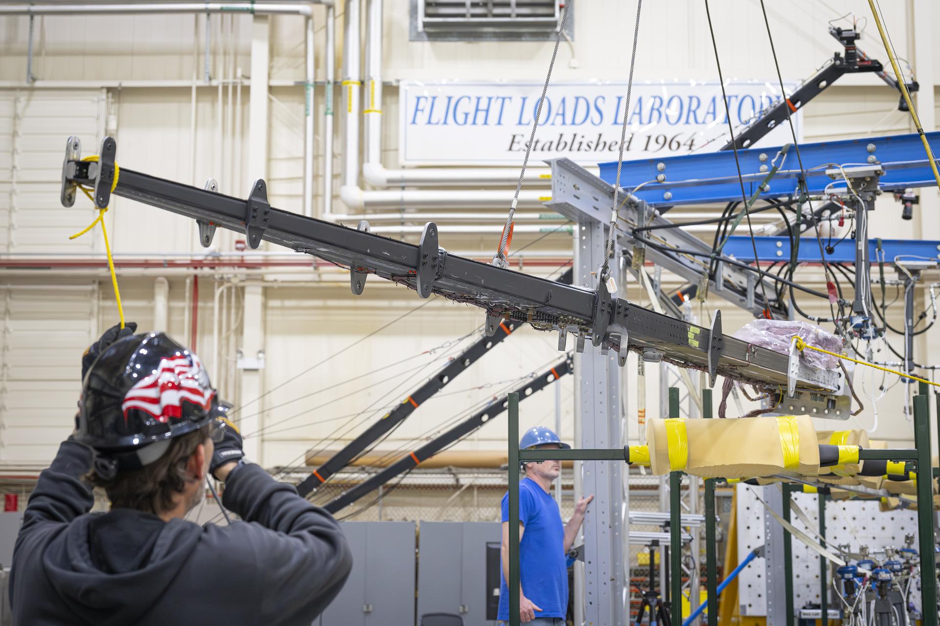
The 15-foot Structural Wing Experiment Evaluating Truss-bracing test article is fully installed in the Flight Loads Laboratory at NASA’s Armstrong Flight Research Center in Edwards, California, on Wednesday, May 20, 2026. The model is part of NASA’s research to develop technologies for future ultra-efficient aircraft.
Credits: NASA/Carla Escamilla
NASA researchers recently put a new wing design, appearing long and thin with a lightweight structural design, through a series of grueling tests to find its structural limits. What they found left them encouraged about the wing’s potential, even when they pushed it past its intended limits.
The 15-foot Structural Wing Experiment Evaluating Truss-bracing (SWEET-15) test article is part of NASA’s research to develop future ultra-efficient aircraft. The design incorporates a long wing supported by an aerodynamic strut, based on NASA’s earlier Transonic Truss‑Braced Wing concept.
The research team is working to understand whether SWEET-15’s design and its new lightweight structural designs could help commercial airliners save fuel. But first, they need to understand how it behaves under the kinds of force wings experience in flight.
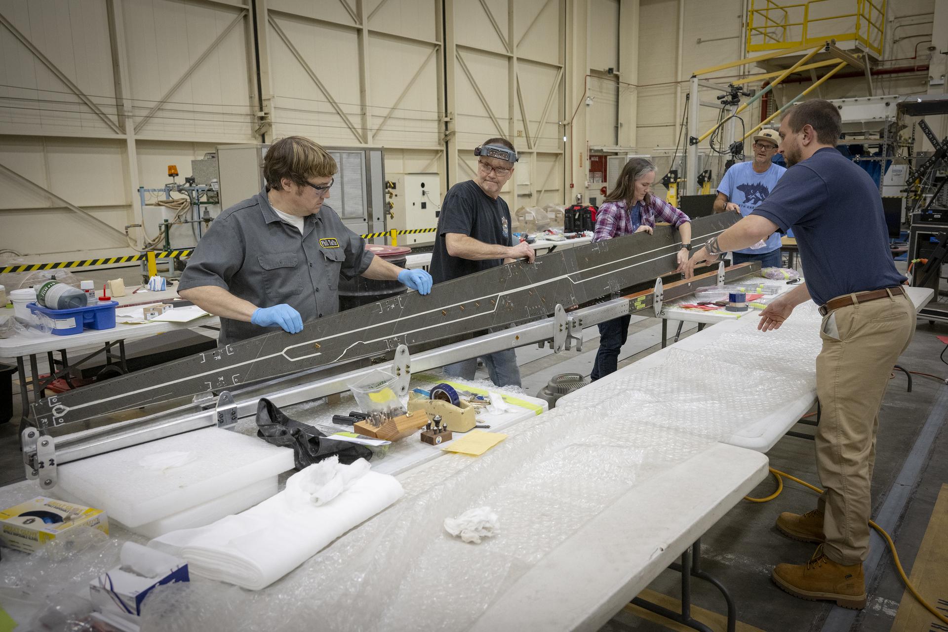
Lab technicians Phil Tofts, Chris McLain, and Jeff Howell and NASA engineers Erin Anderson and Richard Larson prepare the 15-foot Structural Wing Experiment Evaluating Truss-bracing model in the Flight Loads Laboratory at NASA’s Armstrong Flight Research Center in Edwards, California, on Thursday, Dec. 11, 2025. The model is part of NASA’s research to develop technologies for future ultra-efficient aircraft.
NASA/Christopher LC Clark
The SWEET-15 design originated with combining five different advanced composite manufacturing and assembly technologies that enabled the novel structural design. The 15-foot-long test article was then designed and fabricated at NASA’s Langley Research Center in Hampton, Virginia, before traveling to NASA’s Armstrong Flight Research Center in Edwards, California, for testing.
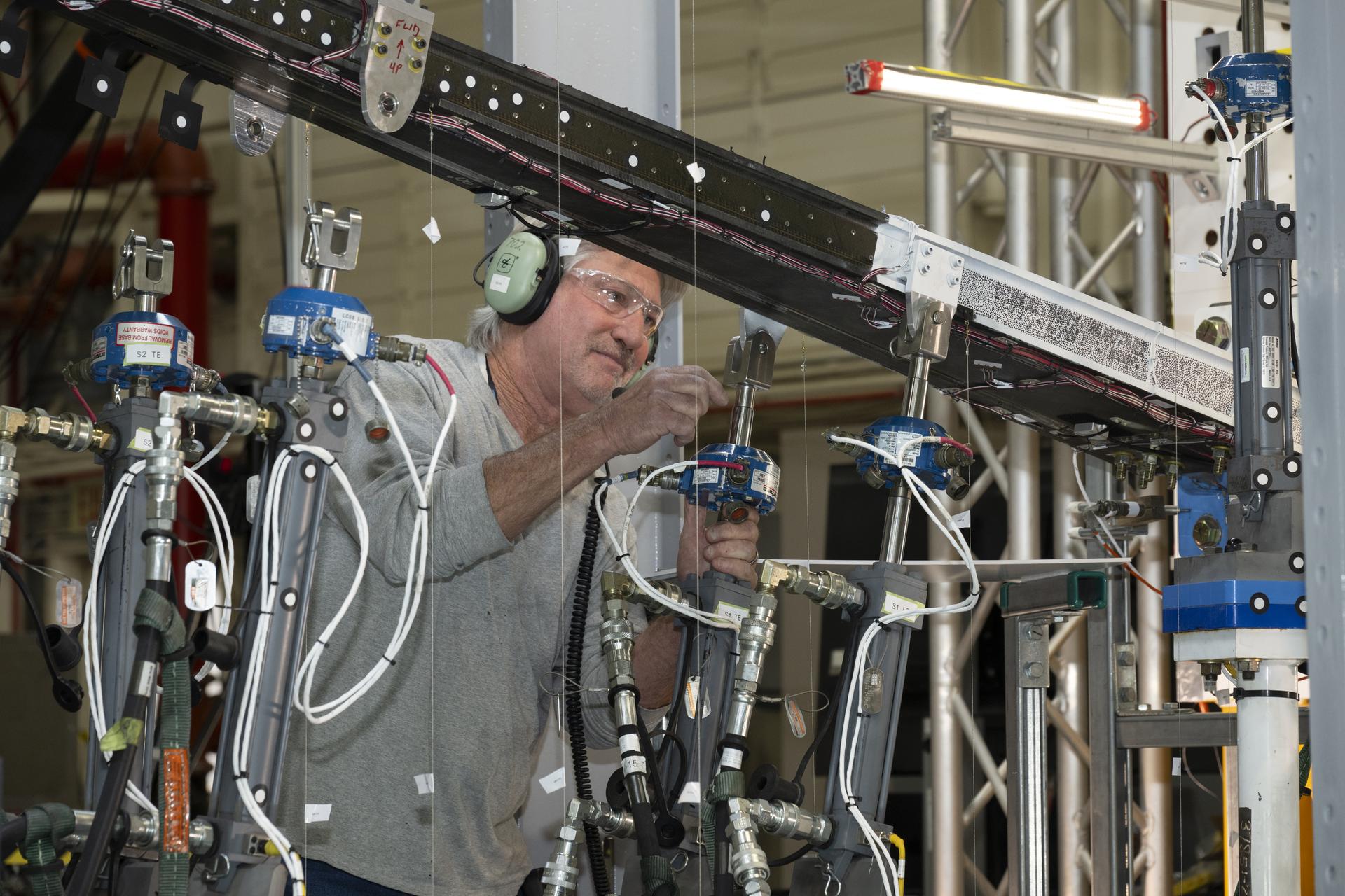
Over several months, NASA engineers intentionally bent the test wing in the Flight Loads Laboratory at NASA Armstrong. Numerous strain and load sensors, including fiber-optic strain sensors, were placed throughout the structure to track how the wing responded as forces increased.
The data from the sensors confirmed the predictions made by NASA’s computer models. According to initial findings, the wing withstood the anticipated in-flight forces without issue. The results provided the team with confidence in the new manufacturing approaches and methods for connecting wing parts used in SWEET-15, which could support future efficient aircraft designs. The manufacturing approach, developed at NASA Langley used the Integrated Structural Assembly of Advanced Composites robot, aims to produce lighter and stronger composite structures for aerospace vehicles.
Lab technicians Jeff Howell, left and Chris Mount install the 15-foot Structural Wing Experiment Evaluating Truss-bracing model in the Flight Loads Lab at NASA’s Armstrong Flight Research Center in Edwards, California, Wednesday, February 11, 2026. The model is part of NASA’s research to develop technologies for future ultra-efficient aircraft.
NASA/Christopher LC Clark
The test concluded with a deliberate test-to-failure, where engineers increased loads beyond the wing’s design limits to determine how and where it would fail. The structure ultimately failed at roughly 127% of its design limit load, with visible damage appearing near the back edge of the wing and in the upper wing cover. This element of testing provided valuable insight into how the joints connecting the wing to its main strut and a secondary one, called a jury strut, behave under forces beyond the expected flight envelope.
This marks the first time a representative composite truss-braced wing configuration has undergone this type of structural evaluation. It was made possible only through NASA collaboration across centers and projects, with researchers utilizing agency resources such as the Fiber Optic Sensing System developed to gather data on both aircraft and spacecraft.
NASA research engineer Walter Hargis regulates the 15-foot Structural Wing Experiment Evaluating Truss-bracing model in the Flight Loads Laboratory at NASA’s Armstrong Flight Research Center in Edwards, California, on Tuesday, March 31, 2026. The model is part of NASA’s research to develop technologies for future ultra-efficient aircraft.
NASA/Ryan Kline
To prepare for the testing, engineers at NASA Langley designed, analyzed, and manufactured the wing and completed safety preparations and lab setup.
Researchers will now analyze the data collected during testing to inform future airframe designs and support NASA’s ongoing efforts to develop more efficient aviation technologies.
The work is being conducted through NASA’s Subsonic Flight Demonstrator project in the agency’s Research Technology Mission Directorate. The successful testing of multiple innovative components marks a milestone in NASA’s aeronautics research.
The Growing Crescent of Mars as NASA’s Psyche Mission Approaches
PIA26586
Credits: NASA/JPL-Caltech/ASU
Downloads
The Growing Crescent of Mars as NASA’s Psyche Mission Approaches
PNG (3.48 MB)
Description
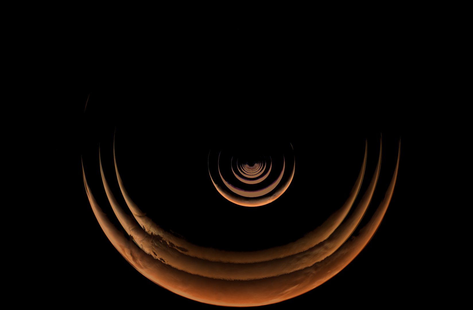
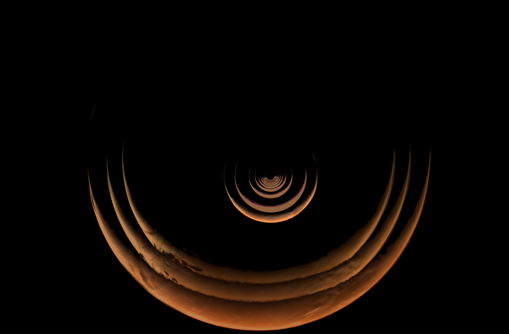
This composite of images taken by NASA’s Psyche mission shows the crescent of Mars grow as the spacecraft approached the planet for a gravity assist from May 2 to May 15, 2026. The series begins with the smallest crescent at the center of the of the image as Mars is farthest from the spacecraft, and progressively grows as the spacecraft gets closer. After these views were captured by the spacecraft’s multispectral imager instrument, Mars began to overfill the field of view as Psyche made close approach with the planet and captured a series of high-resolution images of the surface.
Because Psyche approached Mars from a high phase angle, the planet appeared as a thin crescent in the days running up to the close approach, lit by sunlight reflecting off its surface. Using these views of the approach, close approach, and departure from Mars, the Psyche team compiled a stunning time-lapse of its entire Mars encounter.
For more information about NASA’s Psyche mission, visit:
In April 2026, NASA’s Office of the Chief Health and Medical Officer (OCHMO) initiated a working group to review updated VTE case information, additional data gathered revealing altered blood flow status within a cohort of astronauts, and discuss progress of research and clinical activities intended to mitigate the risk of VTE during spaceflight with new evidence-based clinical practice recommendations.
Recommendations
The following is a summary of the working group’s recommendations:
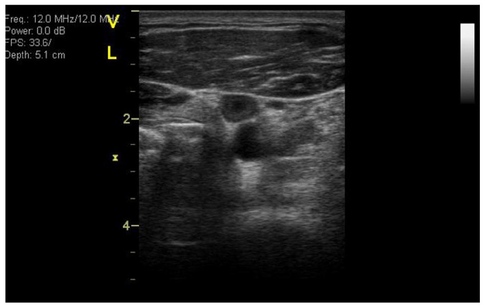
The working group’s conclusions emphasized that stasis in the left internal jugular vein (IJV) is consistently viewed as a dominant risk factor for VTE in microgravity, though there is active debate regarding the relative contributions of slow qualitative flow, endothelial factors and/or retrograde flow.
Limitations of current in-flight ultrasound capabilities to accurately measure stasis/slow flow was cited as a concern, especially if using only stasis as a factor for indicating the need for prophylaxis.
Additional review of assessing stasis with ultrasound in-flight was recommended.
After reviewing the risk factors, additional discussions following the working group led to the majority of the panel agreeing that stasis and retrograde flow warranted use of prophylaxis.
The working group also recommended assessing all other risk factors other than stasis to also determine when prophylaxis is warranted.
Based on a literature review and summary of the panel contributions, a VTE Risk Score for Astronauts Algorithm was developed, which includes providing anticoagulation prophylaxis for stasis alone, or a combination of other thrombosis risk factors that are weighted by terrestrial literature.
Risk of Venous Thromboembolism During Spaceflight
NASA initially formed a working group in October 2024 after diagnosing venous thromboembolisms (VTEs) in astronauts during ISS missions. Experts reviewed case data, updated Clinical Practice Guidelines, and examined possible causes.
NASA has selected Chugach Intelligence Solutions LLC to provide comprehensive operations, maintenance, and repair services for NASA’s Ames Research Center in California’s Silicon Valley.
The Ames Facilities Support Services II contract ensures that the center’s historic and specialized facilities are properly maintained, fully operational, and capable of supporting the agency’s missions and tenant partners in the NASA Research Park.
The hybrid contract has a five-year period of performance, consisting of a 12-month base period and four 12-month option periods, with the possibility of a six-month extension. The performance period is expected to begin Thursday, Aug. 13. The contract includes cost-plus-award-fee core requirements, firm-fixed-price phase-in, and indefinite-delivery/indefinite-quantity task orders, providing flexibility to address both routine and emergent facility needs. The award has a maximum potential value of approximately $158 million, inclusive of all options and total indefinite-delivery/indefinite-quantity ceiling value.
For more information about NASA and its missions, visit:
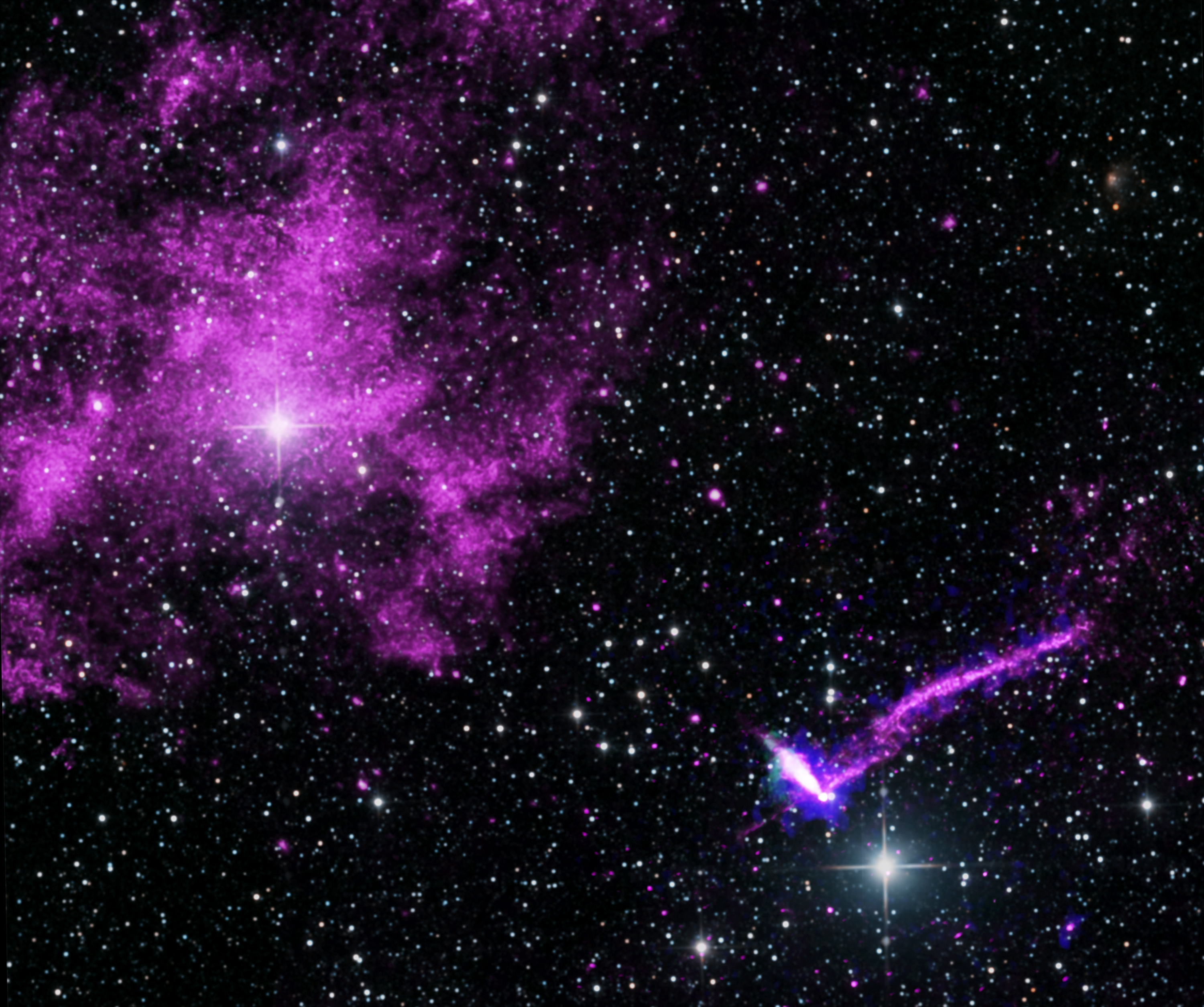
Scientists using NASA’s IXPE (Imaging X-ray Polarimetry Explorer) directly measured the magnetic fields of PSR J1101−6101, a pulsar located within what is often referred to as the “Lighthouse” Nebula, for the first time.
X-ray: Chandra: NASA/CXC/Stanford Univ./J. Dinsmore et al.; IXPE: NASA/MSFC/J. Dinsmore et al., Radio: CSIRO/ATNF/ATCA; Optical: 2MASS/UMass/IPAC-Caltech/NASA/NSF; Image processing: NASA/CXC/SAO/L. Frattare
This composite image, released on July 9, 2026, shows the region around a pulsar – a neutron star with a strong magnetic field that spins incredibly fast – within the Lighthouse nebula. The image contains X-ray data from NASA’s Chandra X-ray Observatory in purple, X-rays from NASA’s IXPE (Imaging X-ray Polarimetry Explorer) in blue, and radio emission captured by the Australia Compact Telescope Array in green.
Scientists used IXPE – for the first time ever – to directly measure the magnetic fields of the pulsar. The results provide new insight into the structure of some of the most extreme objects in the cosmos, as NASA continues to explore the secrets of how the universe works. A paper describing the results published July 9 in the Astrophysical Journal.
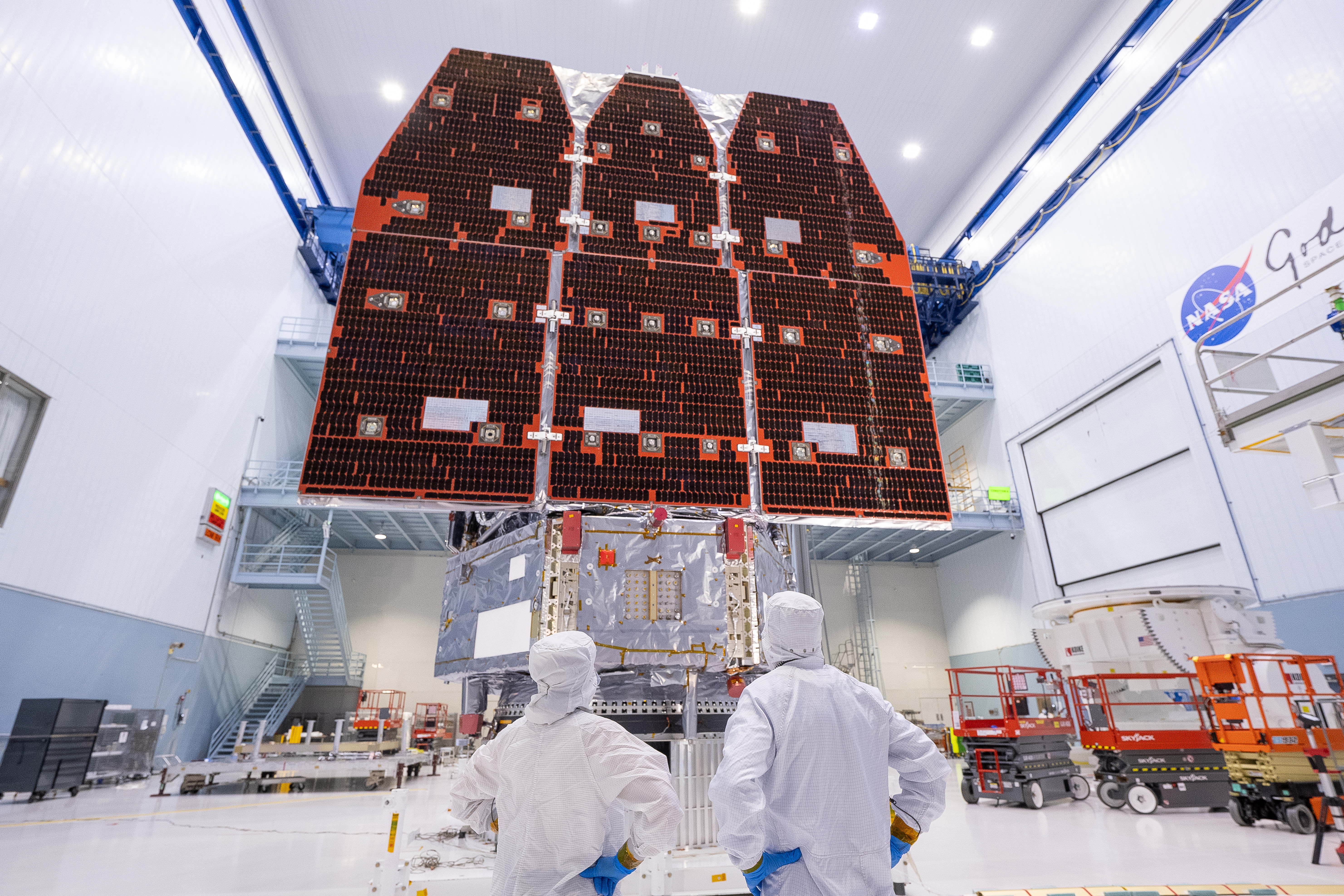
Aquí puede verse el telescopio espacial Nancy Grace Roman de la NASA en la sala limpia del Centro de Vuelo Espacial Goddard de la agencia en Greenbelt, Maryland, donde este observatorio fue construido y sometido a pruebas. Los amplios y profundos sondeos de Roman explorarán la materia oscura, la energía oscura, los exoplanetas y prácticamente cualquier objeto celeste, desde nuestro propio sistema solar hasta galaxias situadas en los confines del universo observable.
Ya está abierto el plazo de acreditación de los medios de comunicación para el lanzamiento de la misión del telescopio espacial Nancy Grace Roman de la NASA.
El lanzamiento del telescopio Roman está programado para no antes de las 7:20 a.m. (hora del este) del domingo 30 de agosto, a bordo de un cohete Falcon Heavy de SpaceX, desde el Complejo de Lanzamiento 39A en el Centro Espacial Kennedy de la NASA en Florida. Este observatorio, que lleva el nombre de la primera astrónoma jefa de la NASA, ofrecerá una visión profunda y panorámica del cosmos, generando imágenes nunca antes vistas que revolucionarán nuestra comprensión del universo.
Los medios interesados en asistir al lanzamiento deben presentar su solicitud antes de los siguientes plazos:
Los representantes de medios de comunicación internacionales sin ciudadanía estadounidense deben presentar su solicitud antes de las 11:59 p.m. del domingo 26 de julio.
Los medios de comunicación de Estados Unidos y los ciudadanos estadounidenses que representen a organizaciones de medios internacionales deben presentar su solicitud antes de las 11:59 p.m. del jueves 30 de julio.•
Todas las solicitudes de acreditación deben ser enviadas en línea a través del sitio web:
The NASA Earth Action Water Resources program area advances the use of Earth science data to support sustainable and adaptable water resources management. Through collaboration with partners, the program area works to enhance water use efficiency, advance water quality monitoring and modeling, and strengthen water resilience. These efforts empower informed decision-making and address critical challenges in water resources.
The NASA Earth Action Health and Air Quality program area encourages the use of Earth observations in air quality management and public health, including environmental health and infectious diseases. The program area helps public health and air quality managers, policymakers, and the public manage health-related decisions and minimize disease risk.
The Energy and Infrastructure program area provides solar, meteorological, and other types of Earth information to aid decision-making related to energy production and management, power systems planning, building energy efficiency and sustainability, and resilient infrastructure. Two major projects are: Prediction Of Worldwide Energy Resources (POWER), which curates satellite and modeling data in free web platforms, and Risk Analysis and Solutions Innovators (RASI), which tailors meteorological and other Earth information to support infrastructure resilience for U.S. communities, especially those surrounding NASA Centers.

 Login