A system will generally move towards equilibrium when a change is made to it in a process called relaxation. To predict the state of the system after some period of time, we only need to know its current state and the external conditions. However, some polymers have memory behaviours where the evolution of the system is not only dependent on the current state, but also on previous states. This is known as the Kovacs effect.
In this work, the researchers investigated the Kovacs effect in a system consisting of suspensions of rod-like nanoparticles. By applying an electric field to these nanoparticles they align, therefore the particles change the liquid’s optical anisotropy, which can be measured as birefringence, which is how the liquid changes light polarization. More birefringence means the particles are more aligned. Importantly, there are faster- and slower-relaxing nanoparticles because of their polydispersity and different sizes, meaning they align at different rates. By changing the strength of the electric field, the faster and slower nanoparticles become out of sync with each other. The future behaviour will then depend on the system’s previous history that is overall hidden by the global birefringence measurement; this is the Kovacs effect.
The researchers modelled the orientational dynamics using the Smoluchowski equation, which describes rotational diffusion of particles. They found that relaxation is not determined by a single timescale or relaxation mode. When some of the modes are fast and some are slow, memory effects will occur. The Kovacs effect is important because it shows that a simple strategy of applying a strong electric field before switching to the target field does not necessarily speed up relaxation. Due to memory effects arising from particles relaxing at different rates, the system overshoots the target state, reducing the expected gain in speed.
To overcome this, the researchers designed improved two- and three-step protocols that suppress the slowest relaxation modes rather than simply matching the average birefringence. These protocols reduce the memory effect, produce a smoother approach to equilibrium, and achieve faster relaxation, although the benefit of additional switching steps becomes progressively smaller. This research improves our understanding of memory effects in complex systems and provides a practical strategy for controlling nanoparticle dynamics more quickly and efficiently.
Topological materials have been receiving a lot of attention in recent years because of their potential applications in future electronic and quantum technologies.
These are a type of material whose electrons have properties that stay stable even when the material has small defects, impurities, or imperfections. They often have surface or edge behaviour that is very different from the interior, because of the structure of the material’s quantum states.
Researchers use quantities such as Berry curvature and Chern numbers to describe topological materials. Berry curvature measures how an electron’s quantum state changes as its momentum changes. Adding this curvature across the whole band gives a Chern number, a whole-number label that can show whether the material is topological.
A key question in this area is: when a material has topological properties, how much of that behaviour is actually tied to quantum entanglement?
In a new paper published recently, Kazuki Ikeda and Steven Rayan tackled this question using the spinless Haldane model. This is a widely used theoretical model for understanding topological materials. This model describes electrons moving on a honeycomb lattice, which has two different sublattices, called A and B.
Here, the researchers added an extra layer of analysis. Instead of only calculating whether the model is topological, they were able to determine where the topological signal comes from.
By introducing a filter based on quantum entanglement, they tested whether the Berry curvature is associated with electron states that are spread across both A and B sublattices, or with states that mostly sit on one sublattice.
They also focused on what happens when the system moves between different topological phases, giving a more organised way to describe what changes when the energy gap closes and the material switches phase.
These results will provide invaluable insights into understanding and designing topological materials going forward.
What’s also interesting here is that, in order to obtain these results, the authors employed Langlands-inspired mathematics to keep track of what changes when the material switches between topological phases.
The Langlands programme is an ambitious mathematical dictionary that tries to translate problems about numbers into problems about symmetry, geometry and analysis.
Although the link in this work is purely conceptual, it does show that Langlands-style structures can organise real physics problems in topological matter.
The fully-integrated LEMS (Lunar Environment Monitoring Station) ready for environmental testing. A small suitcase-size instrument suite built at NASA Goddard, LEMS is designed to carry out continuous, long-term monitoring of the seismic environment at the Moon, including surface motion caused by moonquakes and meteorite impacts in the lunar south polar region.
NASA Goddard/Mike Guinto
NASA has declared “wrenches down” on the first completed payload designed for Artemis astronauts to deploy on the Moon’s surface. Engineers working on NASA’s Lunar Environment Monitoring Station, or LEMS, have completed hardware development and testing and the payload is ready for its permanent home near the lunar South Pole. With the hardware complete, LEMS is ready to support one of the Artemis program’s core goals: enabling sustained lunar science and exploration.
The LEMS instrument package contains two highly sensitive seismometers that will monitor ground vibrations from moonquakes and meteorite impacts, providing scientists with insights into the Moon’s interior and the seismic hazards astronauts might encounter at the surface. Its modular design allows the system to be adapted or expanded to host new instruments in the future, creating a reusable platform that can evolve as scientific priorities grow.
The payload will remain in a clean room at NASA’s Goddard Space Flight Center in Greenbelt, Maryland, where it was built, until it is assigned to an Artemis mission for deployment to the lunar surface.
“The completion of the LEMS scientific instrument is a major step in a new era of lunar surface science. Innovative science experiments will uncover, measure, and reveal the Moon’s secrets while astronauts open new frontiers for discovery,” said Joel Kearns, deputy associate administrator for exploration, Science Mission Directorate, NASA Headquarters in Washington. “And, behind the scenes, countless teams across NASA and our partners are pushing the boundaries of what surface instruments can do, building the tools that will make future exploration possible and safer.”
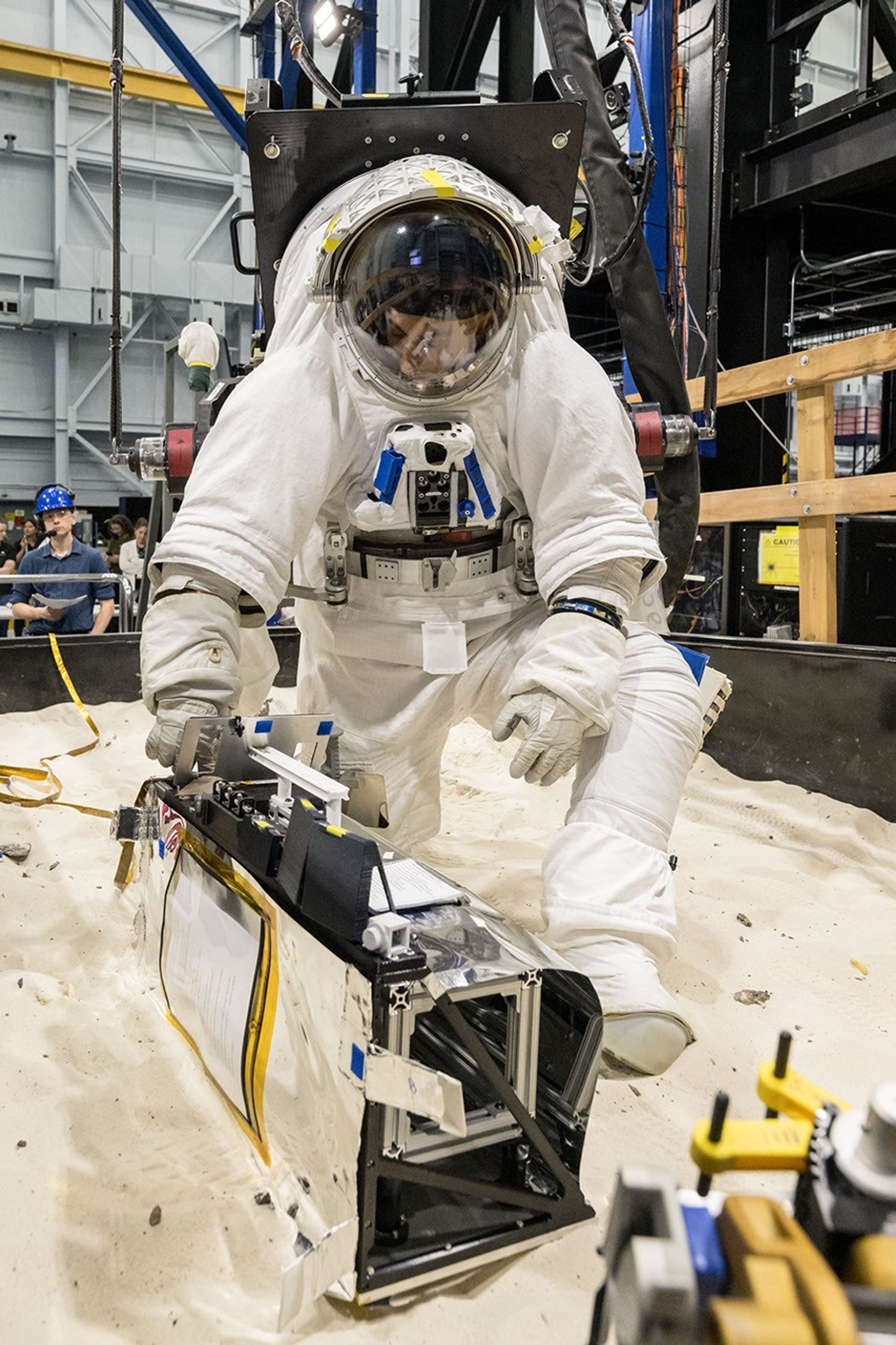
A scientist wearing NASA’s xEMU prototype space suit is testing the handling of a mockup version of NASA’s Lunar Environment Monitoring Station, or LEMS. The testing took place at the Active Response Gravity Offload System, a simulated reduced gravity environment at NASA’s Johnson Space Center in Houston.
NASA Johnson
The LEMS payload builds on a legacy of lunar seismic tracking. Apollo astronauts deployed a network of seismometers on the Moon’s nearside equatorial region between 1969 and 1972. Those instruments operated until 1977, recording about 13,000 moonquakes and other ground vibrations that helped scientists begin to understand the composition of the Moon’s interior. For decades, researchers have hoped to spread more seismometers, updated with new technologies, across the lunar surface.
Now, LEMS will carry the first seismometers to be deployed by future astronauts to listen for faint ground vibrations, collecting new clues to the Moon’s internal structure and ongoing seismic activity. The sensors will be the most compact, sensitive, and energy-efficient seismometers ever built for planetary exploration.
LEMS itself is about the size of a small suitcase, weighing 11 pounds in the Moon’s low-gravity environment. It will carry not just these seismic sensors, but everything it needs to function independently of humans after deployment. LEMS is built to manage its own power production via a lightweight, flexible solar array that conforms to the shape of the LEMS unit. It also will manage its operational activities to ensure continuous data collection based on a preset plan, and monthly data transmission to Earth. The payload will do all this while maintaining a stable internal temperature throughout the massive day-to-night temperature swings of the South Pole region.
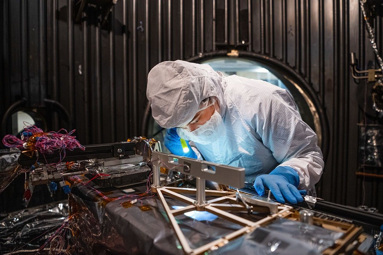
Mechanical Engineer Brie Ludwig inspects the Lunar Environment Monitoring Station (LEMS) in preparation for testing in a thermal vacuum chamber at Goddard Space Flight Center in Greenbelt, Maryland, on March 31, 2026. LEMS is a compact, autonomous, and self-sustaining seismometer suite designed to carry out continuous, long-term monitoring of the lunar seismic environment at the South Polar region.
NASA/Denny Henry
“When we conceived of LEMS, we weren’t just thinking about the next mission, we were thinking about the next generation of lunar exploration,” said Mehdi Benna, a University of Maryland Baltimore County scientist who leads LEMS from NASA Goddard. “Our vision was to create a scientific buoy for the Moon. Like an ocean buoy on Earth, LEMS is designed to be easy to build, adaptable to different scientific objectives, and capable of operating independently for years.”
Before any surface science could happen, Benna and his team had to ensure that LEMS could survive the trip to the Moon and the harsh environment of its surface. Over the past five months, LEMS and its components have been subjected to a demanding series of environmental and operational tests. Engineers verified LEMS can endure the violent shaking of launch, the journey to the lunar surface, and the Moon’s temperature and radiation environment. The team also showed that the instrument package’s mechanical and electrical design is safe for astronaut handling.
The LEMS payload was built to operate through the lunar night, which lasts two Earth weeks, without external power assistance or a heat source. Past lunar surface instruments relied on radioisotope heaters for warmth and power. But LEMS instead will withstand temperatures that dip to minus 400 degrees Fahrenheit in some areas by using advanced insulation materials, low-thermal-conductivity cables that minimize heat loss, and a thermal regulator that conducts heat away during the day to prevent overheating and helps retain heat at night.
These innovations reduce mass and power needs, setting the stage for lighter, energy-efficient instruments that can operate continuously at future Artemis landing sites and the NASA-led Moon Base.
The LEMS payload is led by University of Maryland Baltimore County and University of Maryland College Park. Technical implementation is led by NASA Goddard. The University of Arizona, in partnership with Silicon Audio, Inc., supplied LEMS’ two state-of-the-art seismometers. Morehead State University in Kentucky provided LEMS’ telecommunication system and will operate the instrument on the surface. Washington University in St. Louis will manage the instrument’s data processing and dissemination to the larger scientific community.
NASA Telescopes Create Colorful ‘Craft’ From Nearby Nebula
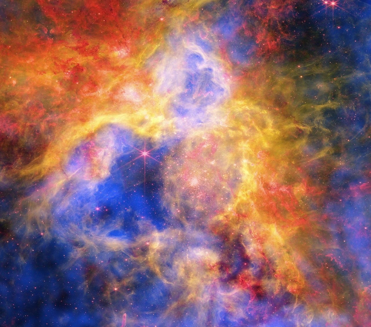
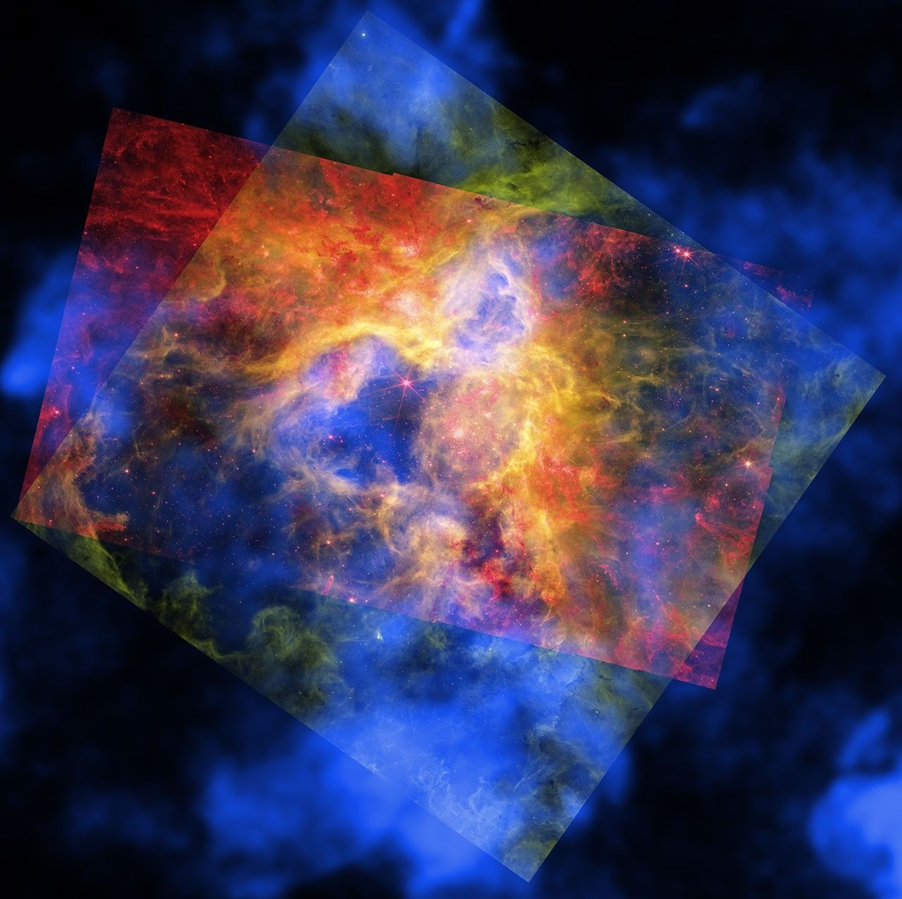
Like a collage made of layered sheets of colored cellophane, a vibrant new image layers observations of a famous star-forming nebula from NASA space telescopes. The resulting cosmic “craft” reveals new details about the star formation region known as 30 Doradus, or the Tarantula Nebula.
Located in the Large Magellanic Cloud, a small neighbor galaxy to the Milky Way about 160,000 light-years from Earth, the Tarantula has thousands of young stars embedded in a vibrant honeycomb-like structure of gas and dust.
X-ray: NASA/CXC/Ohio State Univ./J. Rodriguez et al; Infrared: NASA/ESA/CSA/STScI; Optical: NASA/ESA/STScI; Image Processing: NASA/CXC/SAO/P. Edmonds
Like a collage made of layered sheets of colored cellophane, a vibrant new image layers observations of a famous star-forming nebula from NASA space telescopes. The resulting cosmic “craft” reveals new details about the star formation region known as 30 Doradus, or the Tarantula Nebula.
Located in the Large Magellanic Cloud, a small neighbor galaxy to the Milky Way about 160,000 light-years from Earth, the Tarantula has thousands of young stars embedded in a vibrant honeycomb-like structure of gas and dust.
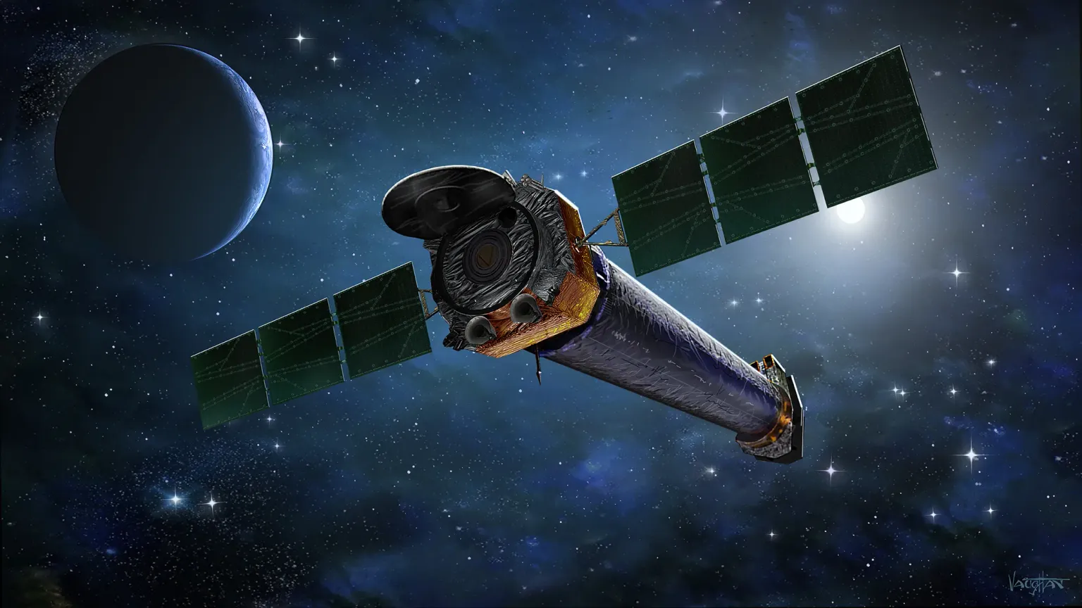
The new composite image contains X-rays from NASA’s Chandra X-ray Observatory, which has repeatedly observed the Tarantula Nebula over the course of its mission, in the layer that appears in blue. The X-ray data reveals gas blown away by winds from the surfaces of young, massive stars and heated to millions of degrees by shock waves, like sonic booms from supersonic jets.
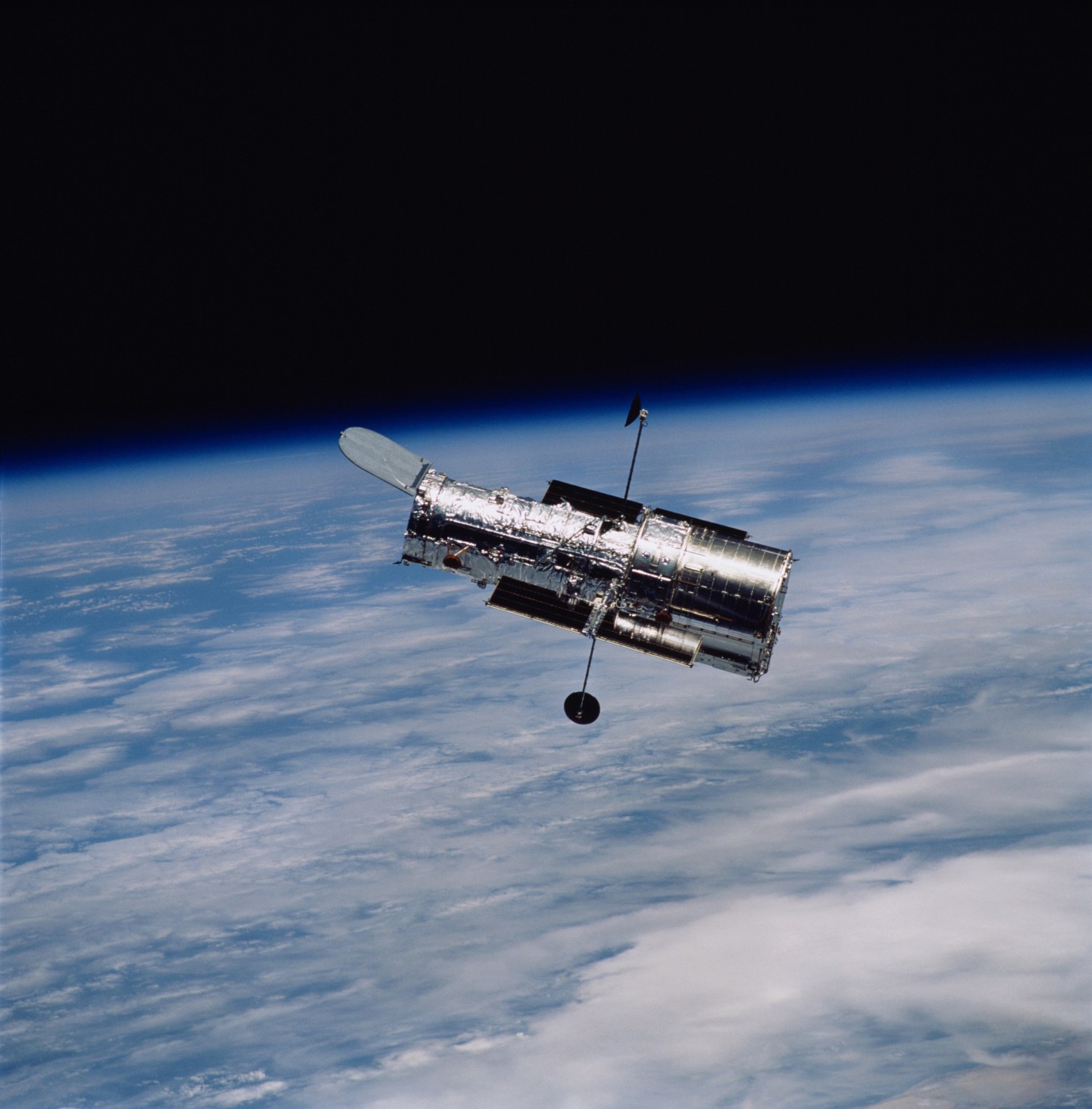
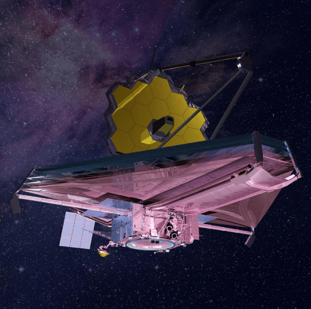
The red represents infrared data from NASA’s James Webb Space Telescope showing thousands of young stars, plus swaths of cool dust that will provide the ingredients to form new stars and planets. Optical data in the green layer from NASA’s Hubble Space Telescope uncovers hydrogen gas that is warmer than seen with Webb, as well as some individual stars through the nebula.
The composite image shows the full Hubble and Webb images of this region, as well as a large section of the Chandra image, all recently published in a research paper in the Astrophysical Journal. In some regions the blue Chandra layer stands alone, and in others it combines with either the red Webb data or the green Hubble data. In the middle region all three images overlap to provide a holistic view in red, orange, yellow, green, and blue.
Previously, astronomers had studied the amount and the impact of energy produced by winds from young, massive stars in the Tarantula Nebula. Scientists expect that much of this energy should heat gas so that it produces X-rays. However, the research paper shows that there is much less X-ray-emitting gas in the nebula than expected. This led researchers to ask: Where has this energy gone and what tamed the Tarantula Nebula?
By studying the data from Chandra, Hubble, and Webb, combined with data from NASA’s retired Spitzer Space Telescope, the team concluded the Tarantula may be losing energy from several sources.
First, up to half of the hot gas is leaking through the shell walls of the gas and dust structures and escaping the nebula. Next, there is stirring and mixing between the cold gas near the shell walls and some of the hot gas, lowering the overall temperature of the gas. Finally, comparisons with computer simulations suggest the Tarantula may be losing energy through conduction. This involves direct physical contact between hot and cooler material, like with a frying pan on a burner, causing the hot and cooler material to equalize in temperature. In the case of the Tarantula Nebula, the hot gas would be conducting heat by being in direct contact with the cooler gas in the shells, especially in the densest regions. This scenario does not necessarily involve mixing the hot and cooler gas.
The combination of these three channels for losing large amounts of energy leads to this colorful and complex display revealed by NASA’s telescopes working together.
Tarantula Nebula / 30 Doradus, cropped version.
X-ray: NASA/CXC/Ohio State Univ./J. Rodriguez et al; Infrared: NASA/ESA/CSA/STScI; Optical: NASA/ESA/STScI; Image Processing: NASA/CXC/SAO/P. Edmonds
The paper describing these results was led by Jennifer Rodriguez of The Ohio State University in Columbus. Additional authors on the paper include Laura Lopez, Ohio State; Lachlan Lancaster, Columbia University in New York City; Anna Rosen, San Diego State University; Omnaraynai Nayak, Space Telescope Science Institute in Baltimore; Sebastian Lopez, Ohio State; Tyler Holland-Ashford, NASA’s Goddard Space Flight Center in Greenbelt, Maryland; and Trinity Webb, Ohio State.
NASA’s Marshall Space Flight Center in Huntsville, Alabama, manages the Chandra program. The Smithsonian Astrophysical Observatory’s Chandra X-ray Center controls science operations from Cambridge, Massachusetts, and flight operations from Burlington, Massachusetts.

 Login