 Login

Google AI and the End of Search as We Know It
Google AI is transforming Search from a list of links into an AI-powered answer engine, reshaping visibility, trust, and web traffic.

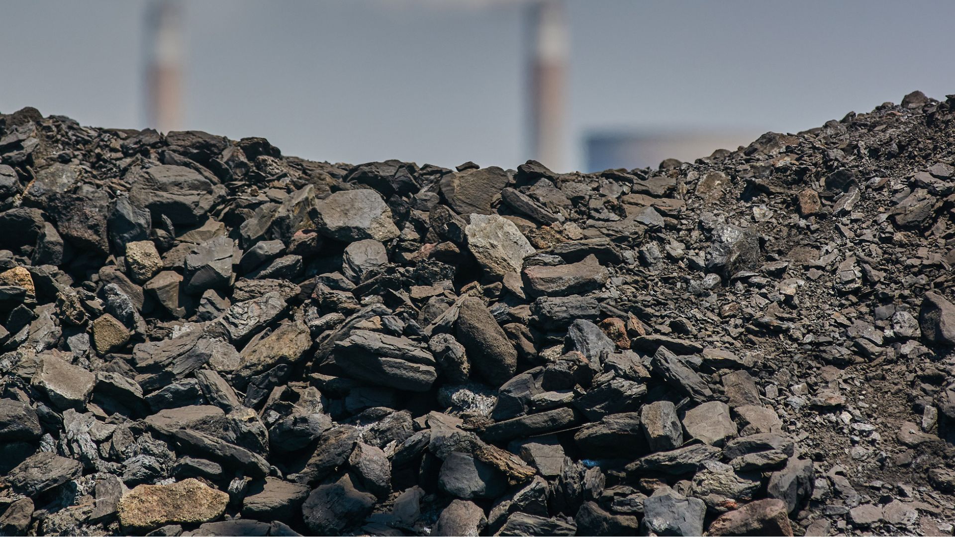
China is turning the massive environmental liabilities of its coal-mining history into the raw materials for its next generation of infrastructure.
In the southeastern county of Gaoping, located deep within China’s premier coal province of Shanxi, a massive new recycling facility has quietly begun operations. It transforms the waste into high-value industrial and building materials.
Reportedly, its daily output sounds like a standard quarry operation: 1,000 tonnes of sand, gravel, and unburnt bricks destined for the country’s endless appetite for concrete.
But these construction materials did not come from a riverbed or a mountain quarry. The material was extracted from coal gangue, which is the ultra-hard, toxic rock waste left behind after mining and washing coal.
China’s coal gangue is expected to be around 7 billion tonnes. Left unmanaged, coal waste routinely triggers water contamination, airborne dust pollution, and spontaneous fires.
Less than 60 percent of this mountain of rock was ever reused. The rest stayed behind as a permanent ecological tax on resource-dependent cities. Now, technology is cracking that stubborn bone to turn the waste into an industrial resource.
The South China Morning Post (SCMP) reported that the Gaoping facility consists of automated systems that sort the incoming waste using X-ray separation equipment. From there, the material is crushed, screened, and stripped of impurities. The result is a stream of manufactured aggregates and eco-friendly unburnt bricks that skip the high-emission firing process entirely.
Local authorities say the applications reach far beyond basic roads. The refined waste is finding its way into ceramics and even high-tech spacecraft coatings.
Beyond recycling coal waste, China is eyeing a broader circular economy to overhaul its construction material supply.
China uses nearly half of the world’s construction sand and gravel, a habit that has severely degraded fragile river ecosystems. Replacing natural sand with coal waste solves two environmental headaches at once.
Research also suggests that recycling construction and demolition waste could meet half of China’s aggregate demand by 2050.
The industry is scaling up at breakneck speed. While attempts to recycle gangue date back to the 1950s, the economic incentive shifted after 2010 as natural sand supplies tightened and Beijing locked in its national carbon targets.
Last year, a milestone 10-million-tonne utilization project was launched in Datong.
The strategy is not without its speed bumps. Industry experts caution that aggregates derived from coal waste currently represent only a tiny sliver of China’s annual consumption.
Due to the material’s structural limitations, it cannot be used for high-strength or critical load-bearing structures like skyscraper pillars or major bridges. Strict toxicity testing is also mandatory to ensure heavy metals do not leach out of the residential walls of the future.
This strategy operates alongside efforts to harvest industrial value from existing fossil fuel liabilities—such as extracting critical technology metals like lithium, gallium, and germanium from mining byproducts. Furthermore, trapping power plant emissions to manufacture affordable agricultural fertilizer.
The development shows that a zero-waste future might actually be possible simply by turning a toxic liability into literal building blocks.

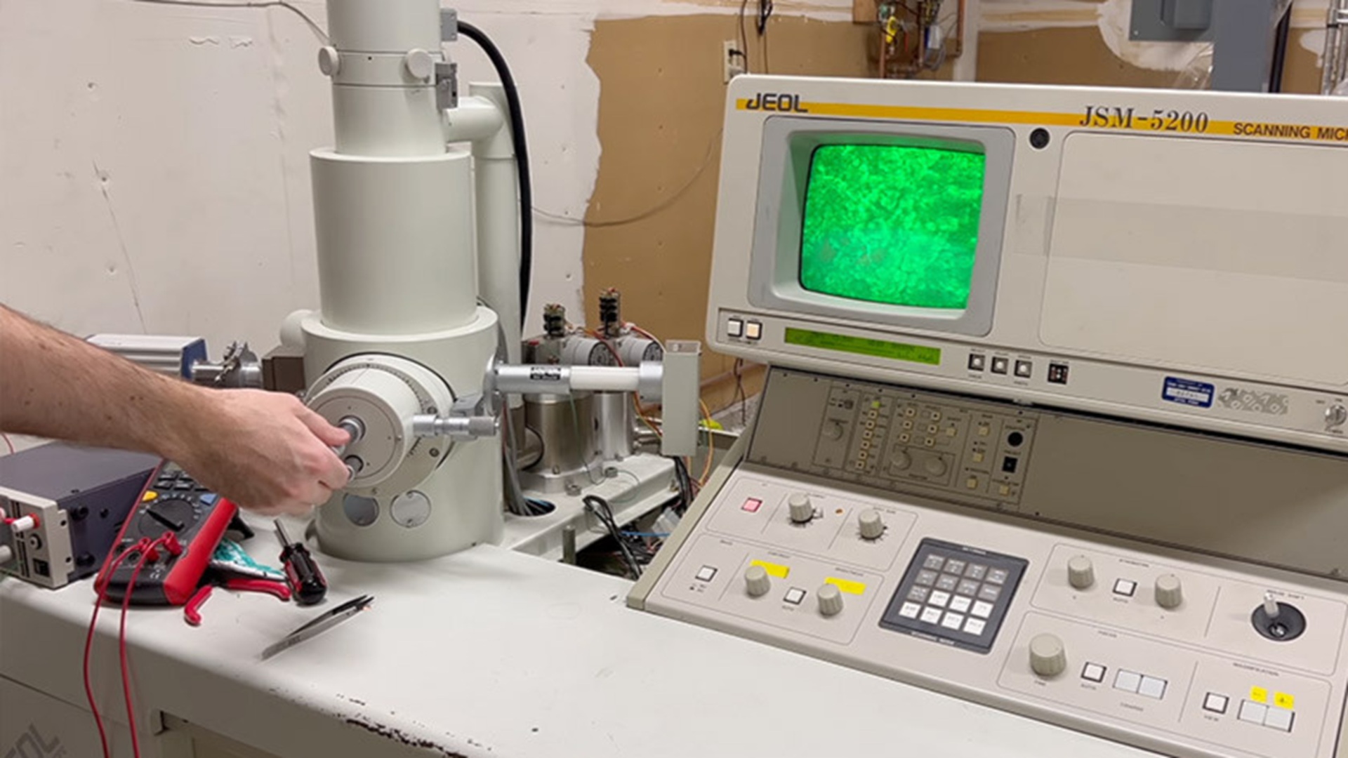
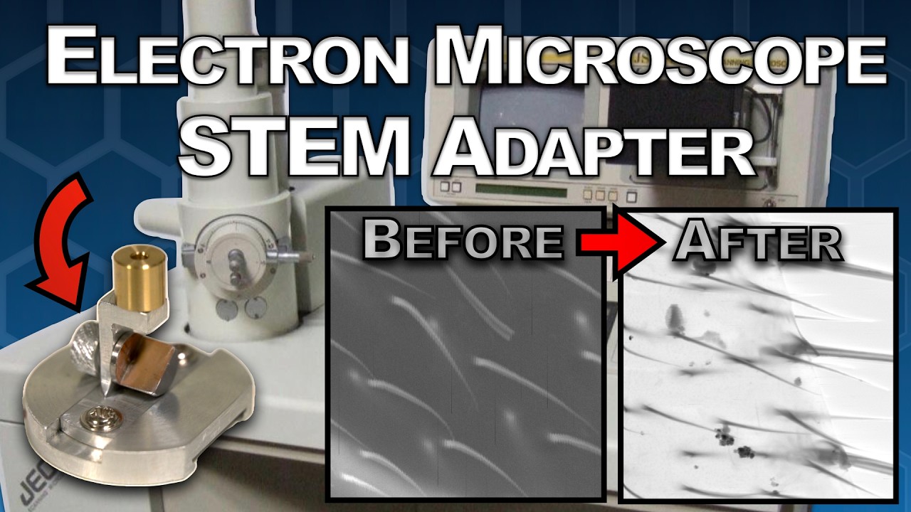
A home machinist and microscopy enthusiast has documented a detailed technical conversion of a scanning electron microscope (SEM) into a transmission electron microscope (TEM), demonstrating that sub-nanometer resolution imaging is not strictly confined to professional laboratory settings.
The project walks through the mechanical, electronic, and optical modifications required to redirect the SEM’s focused electron beam through an ultrathin specimen rather than bouncing it off a surface.
In a conventional SEM, a focused electron beam rasters across the surface of a sample and detectors collect secondary and backscattered electrons to construct a three-dimensional surface image.
A TEM, by contrast, accelerates electrons through a thin specimen—typically below 100 nanometers—and a detector or phosphor screen on the far side captures the transmitted beam, yielding internal structural information at atomic or near-atomic resolution.
The two modalities require fundamentally different sample preparation, detector geometry, and beam alignment strategies, which makes the conversion non-trivial.
The modification involved fabricating a custom specimen holder stage capable of holding electron-transparent samples, repositioning a scintillator-based detector beneath the sample plane, and carefully adjusting beam convergence angles to suit transmission geometry.
Beam energy in the converted system reportedly remained in the range typical of low-voltage SEMs—roughly 5 to 30 kiloelectron volts—which is lower than the 80–300 keV found in dedicated TEMs.
That energy gap has direct consequences for penetration depth and contrast, meaning the converted instrument is better suited to very thin biological or polymer films than to hard crystalline materials.
At 30 keV, electron penetration through matter is substantially reduced compared to a 200 keV research-grade TEM. Specimens must be prepared to thicknesses well below 50 nanometers to achieve meaningful transmission contrast, which demands either focused ion beam (FIB) thinning or careful ultramicrotome sectioning.
The project does not sidestep this limitation; the builder acknowledges that sample preparation remains the most labor-intensive part of the workflow and that certain dense or thick materials will simply block the beam entirely at these voltages.
Achieving proper alignment in a converted system also presents practical difficulties. Commercial TEMs incorporate sophisticated electromagnetic lens alignment systems, stigmators, and beam-tilt controls that are absent in most SEMs. The DIY conversion relies on mechanical stage adjustment and iterative beam tuning to compensate, which increases setup time per sample significantly.
The transmitted electron signal was captured using a scintillator coupled to a camera placed below the sample stage. This configuration is conceptually similar to a bright-field TEM detector arrangement, where areas of the specimen that scatter or absorb electrons appear darker against a bright background.
The resolution achievable with this setup is constrained not only by beam energy but also by the point spread function of the scintillator material and the pixel pitch of the camera sensor used.
For engineers interested in electron optics at the amateur level, projects like this one sit alongside other low-cost electron beam experiments that have appeared in the maker community.
DIY scanning electron microscope builds have previously demonstrated that fundamental vacuum and high-voltage engineering skills can be acquired outside institutional settings, though always with serious attention to X-ray shielding and high-voltage safety protocols.
Operating any electron beam instrument outside a certified laboratory introduces real hazards. Bremsstrahlung X-ray emission is an inherent byproduct of electron deceleration in the target and chamber walls.
SEMs are shielded from the factory, but any modification to the chamber geometry—including cutting ports for a transmission detector—requires careful verification that shielding integrity is maintained. The builder’s documentation should be read with this in mind by anyone considering replication.
The conversion represents a technically detailed exercise in applied electron optics and vacuum engineering, and it offers a practical reference point for understanding the design constraints that separate entry-level and research-grade electron microscopy instruments.

A new type of radar to detect drones nearby ports, vessels, harbours, and critical maritime infrastructure has been introduced. Developed by Robin Radar Systems, IRIS OTM at Sea is designed for seamless land-to-sea deployments.
The new system is a major expansion of its IRIS On-The-Move (OTM) capability.
The comprehensive update is aimed at strengthening counter-UAS protection for shipping lanes, naval operations, and coastal assets.
“What we are seeing globally is that the drone threat is no longer confined to the battlefield or to land-based infrastructure. Shipping lanes, ports, harbours and offshore assets are now all exposed to low-cost aerial threats that can disrupt trade, damage infrastructure and threaten civilian safety,” said Siete Hamminga, CEO, Robin Radar Systems.
“The Strait of Hormuz has once again demonstrated how vulnerable critical maritime corridors can become during periods of instability. IRIS OTM at Sea is being designed to answer that challenge with a rapidly deployable, software-defined capability that can move seamlessly between land and sea.”
Originally developed to operate from moving land vehicles traveling at speeds exceeding 62 mph (100km/h), IRIS On-The-Move will now be adapted for maritime environments through advanced software enhancements that compensate for sea clutter, vessel movement, and challenging coastal conditions, according to a press release.
Designed to be mounted on vessels, IRIS OTM at Sea will detect, track, and classify drones while travelling at speeds of up to 54 knots, operating effectively in extreme environments thanks to its salt- and corrosion-resistant engineering, resonance tolerance, and EMC-compliant architecture.Unlike traditional static radars, IRIS is designed to move with the threat itself, providing persistent situational awareness across highly dynamic environments, as per the release.
The company revealed that the radar’s software architecture will be updated to filter out heavy sea reflections and environmental clutter to isolate small airborne threats operating close to the waterline, an increasingly important capability as drone incursions continue to evolve across maritime theatres.
Robin Radar Systems highlighted that the maritime update has been shaped directly by operational lessons from ongoing live-fire environments, where the need for flexible, mobile counter-UAS systems capable of protecting dynamic environments has accelerated dramatically. The company’s engineering teams reportedly adapted the system specifically to address the increasing use of fixed-wing drones and low-altitude aerial threats around strategic shipping corridors and maritime infrastructure.
“Modern security demands speed and flexibility. Operators need systems that can deploy quickly, integrate easily, and adapt as threats evolve,” said Vivien Croes, Chief Technical Officer, Robin Radar Systems.
“What makes this update important is that we are taking a combat-proven radar and extending its capabilities into one of the most operationally complex environments in the world. The future of counter-UAS is not static infrastructure, it is agile, mobile sensing systems capable of protecting people, critical infrastructure and global commerce wherever threats emerge.”
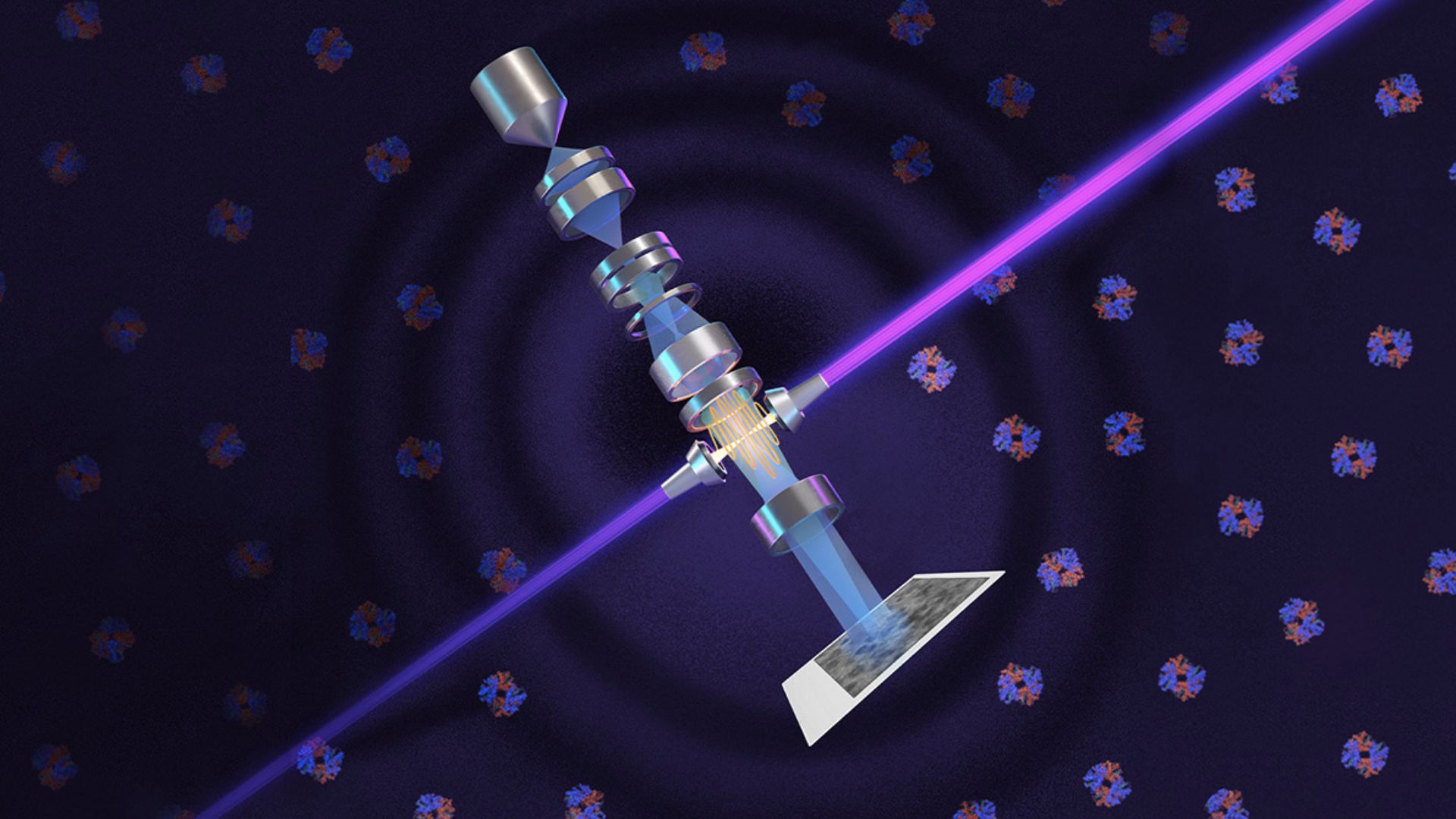
Researchers in the United States have built a technology that boosts the performance of electron microscopes. Berkeley Lab and UC Berkeley physicists’ new technique offers detailed images of the small molecules and cell structures that are crucial to understanding biology and disease.
They have adapted the phase-contrast technique to cryo-electron microscopy (cryo-EM), which has about 10,000 times the magnification of light microscopy. Their laser-based phase plate produces sharp images of molecules that today’s cutting-edge cryo-EM systems struggle to capture.
The research team revealed that the new technology was brought to fruition by more than 15 years of theoretical and experimental work by leading microscopy scientists, collaboration with expert machinists, and support from Biohub.
The phase plate is paired with a new, custom Thermo Fisher Scientific microscope that was developed to maximize the benefit of the plate’s ultra-bright laser. Images taken by the system are notably clearer and sharper and contain greater detail that structure-solving software can process to generate more accurate atomic models of the molecules captured, according to a press release.
“Theia is the Formula 1 of microscopes. It has better resolution than the standard cryo-EM, even without the laser. With the addition of the laser phase plate, we hope that it really becomes one of the world’s best instruments overall,” said Holger Müller, a UC Berkeley professor of physics and faculty scientist in Berkeley Lab’s Biosciences Area who led the development effort.
“Before, studying structures with cryo-EM was like trying to look at paintings in a dark gallery. With Theia, it’s like the lights have been turned on for the first time.”
The team also demonstrated the system’s power by imaging aldolase, a protein in muscle that is relatively easy to capture with today’s cryo-EM machines, and hemoglobin — a protein that carries oxygen in blood. Hemoglobin is a smaller protein that sits at the lower size limit for current machines and is often used as a benchmark for cryo-EM performance. The laser-phase plate improved the resolution of the protein structure in both cases, but more so for the hemoglobin.
“We had a whole spectrum from larger particles that are not that challenging with extremely good specimen preparation to challenging small particles with bad preparation. Of course, the better the specimen, the less important it is that you have a top microscope. It was the most challenging ones is where we see the strongest improvements,” said Müller.
The system is currently installed at UC Berkeley, and the team is now working to expand the microscope beyond single-particle analysis to perform a newer technique referred to as cryo-electron tomography (cryo-ET).
Similar to how CT (computed tomography) scans at the hospital generate images of body parts, cryo-ET assembles different angular views of a molecule or cellular structure into a 3D image. Cryo-ET will provide a huge leap in scientists’ ability to study cellular processes because it captures molecules in their natural states inside cells, unlike single-particle cryo-EM, and offers much higher resolution than light microscopy, as per the release.
