❌

Reading view

Observers Beware: Reflect Orbital’s Space Mirrors Approved for Launch

The Federal Communications Commission (FCC) has approved the launch of Reflect Orbital's Earendil 1 satellite — a space mirror 18 meters wide designed to reflect sunlight to the ground.

The post Observers Beware: Reflect Orbital’s Space Mirrors Approved for Launch appeared first on Sky & Telescope.

  •  

When the Spacecraft Align: Rescuing Saturated Images of Solar Flares

close-up image of the Sun showing a solar flare

Many observations of solar flares suffer from saturation and blooming, causing crucial information to be lost. Researchers recently validated a technique for retrieving information from saturated flare images, unlocking a treasure trove of powerful solar flares for examination.

Solutions for Saturation

Since 2010, the Atmospheric Imaging Assembly (AIA) on the Solar Dynamics Observatory (SDO) has been capturing nearly continuous extreme-ultraviolet images of the Sun’s disk, revealing our star’s dramatic high-energy behavior. Though SDO/AIA’s observations have transformed our understanding of the Sun’s activity, they have limitations: powerful solar flares can saturate the detector, spilling charge into nearby pixels.

This saturation and overflow compromises our ability to study the most energetic solar flares — but the “lost” information may actually be recoverable. When light from an intense flare enters SDO’s instruments, not all of it pools in the saturated region of the detector: some of the light is diffracted by the optics, and by mathematically inverting this pattern of diffracted light, researchers can attempt to extract the encoded information about the saturated region. Researchers have used this technique for more than a decade, but options for validating the results were limited until now.

Solar Orbiter Lends a Hand

Launched almost 10 years to the day after SDO, the Solar Orbiter spacecraft provides an excellent opportunity to test inversion techniques for recovering information from saturated solar images. Solar Orbiter’s Extreme Ultraviolet Imager snaps brief photos of the Sun at a rapid cadence, and its images remain unsaturated even when faced with energetic solar flares.

positions of Solar Dynamics Observatory and Solar Orbiter during a solar flare on 19 March 2024

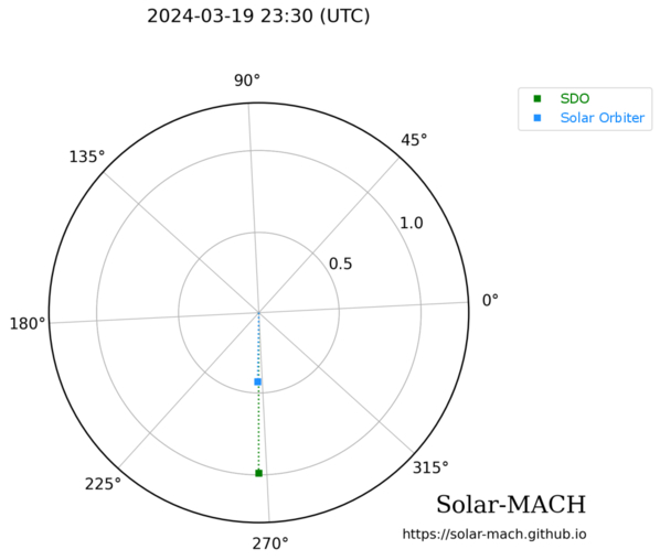
Positions of SDO (green) and Solar Orbiter (blue) during a solar flare on 19 March 2024. Click to enlarge. [Guastavino et al. 2026]

As described in a recent research article by Sabrina Guastavino (University of Genoa; Italian National Institute for Astrophysics) and collaborators, the ideal setup for testing the inversion technique arose on 19 March 2024, when SDO and Solar Orbiter both viewed a solar flare while separated by just 1 degree in longitude.

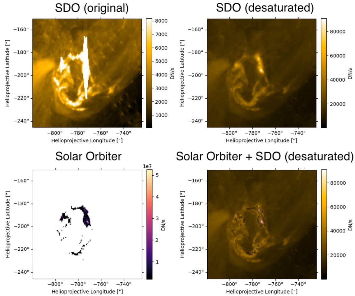
Guastavino’s team aligned and reprojected the data, accounting for the slightly different viewing angles of the two spacecraft, then applied an algorithm called Adaptive SE-DESAT to reconstruct the flux within the saturated portion of the SDO image. The team compared the desaturated SDO images to the unsaturated Solar Orbiter images over the course of the flare, finding the same flare morphology and similar time evolution between the two data sets.

sample results of the desaturation process

Example of unprocessed SDO data (top left), desaturated SDO data (top right), Solar Orbiter data (bottom left), and a combination of the two data sources (bottom right). Note that the Solar Orbiter observations have been clipped so that only the highest flare intensities were recorded. Click to enlarge. [Adapted from Guastavino et al. 2026]

A Treasure Trove of Desaturated Data

Overall, these results demonstrate the effectiveness of the inversion technique, though Guastavino and coauthors noted that improvements could be made during the impulsive phase of the flare, when the emission is increasing. The team identified several reasons why the results may not match during this phase, including rapid evolution of the flare during individual exposures.

Despite these areas that require further attention, the validation of this technique unlocks 16 years of solar flare observations from SDO. This especially enhances our sample of powerful solar flares, increasing the available records of the most energetic solar flares by orders of magnitude.

Citation

“Validation of an Extreme-Ultraviolet Desaturation Technique for the Atmospheric Imaging Assembly on Board the Solar Dynamics Observatory Using Observations from the Extreme Ultraviolet Imager on Board Solar Orbiter,” Sabrina Guastavino et al 2026 ApJL 1005 L50. doi:10.3847/2041-8213/ae7d2e

The post When the Spacecraft Align: Rescuing Saturated Images of Solar Flares appeared first on AAS Nova.

  •  

Putting the Landing Site Before the Lander

An oblique-angle photograph of a deep crater half in shadow.

NASA is once again sending scientific missions to the Moon. But under the new commercial framework for getting there, researchers need to invent a new method for how to pick where to land.

A New Process for Picking Sites

NASA’s Commercial Lunar Payload Services program is a bold innovation in organizing robotic missions to the Moon. Under this model, rather than keeping the mission process entirely in-house, the agency selects the scientific mission they want to support then simply buys a ride to the lunar surface from a commercial vendor. But, how do you pick a landing site before you know exactly how you’re getting there?

A photograph from orbit of two volcanic mounds on the moon.

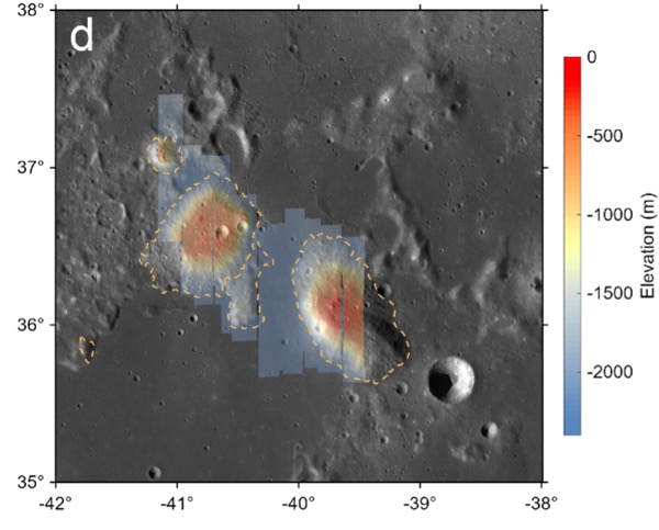
The Gruithuisen domes region, the broad area the Lunar-VISE team searched for potential landing sites. Click to enlarge. [Adapted from Williams et al. 2026]

The Lunar Vulkan Imaging and Spectroscopy Explorer (Lunar-VISE) mission, set to launch in mid-2028, was one of the first programs to go through this new landing site selection process. After being officially selected in 2022, the team had just nine months to nail down exactly where their mission should touch down. A recent article led by Jean-Pierre Williams (University of California, Los Angeles) detailed exactly how the team accomplished this task and presented some lessons they learned along the way.

No Parking Lots on the Moon

Picking a landing site is no small task: for context, selecting the landing sites for each of the most recent Mars rovers took five years and multiple community workshops. The Lunar-VISE team therefore took a streamlined and logic-driven approach. They started by explicitly laying out their science objectives: Lunar-VISE’s purpose is to investigate some strangely silicate-rich volcanic formations called the Gruithuisen domes, so they had to land either on or near those. They also had to have access to boulders that were excavated from deep within the domes during a crater formation event, so they had to pick a spot with boulders relatively nearby.

In addition to objectives, they also laid out a slew of constraints. Although they needed boulders nearby, they couldn’t have too many boulders, or any particularly large boulders, since those could pose hazards for landing. There also couldn’t be any steep slopes in the field. Most of the area had to maintain a line of sight with a supporting orbiter for communications, so they couldn’t set down near any ridges. Also, they had to consider how the terrain would cast shadows as the lunar day progressed, since they didn’t want their mission cut short by freezing temperatures and a lack of solar power. As the team quipped, “many interesting, high-science value locations on the Moon may not be in proverbial ‘parking lots.'”

A low-angle photo of a crater and plain on the moon, with arrows and annotations to the landing ellipse, boulders, and the edge of the dome.

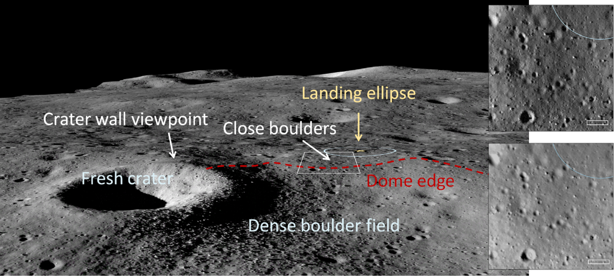
An image from the Lunar Reconnaissance Orbiter overlaid onto a terrain model of the final landing site. Click to enlarge. [Williams et al. 2026]

By combing through archival data and working with the team that operates the Lunar Reconnaissance Orbiter Camera, a key asset for making detailed maps of the Moon, the researchers found the perfect spot: alongside a 190-meter-diameter crater named Mareta. This feature is named after Mareta West, one of the first female planetary geologists at the United States Geological Survey and the scientist who selected the landing site for Apollo 11’s historic touchdown.

In addition to presenting their landing site, the researchers offered a handful of lessons to others who may someday be in the fortunate and thrilling position of needing to pick a landing spot on the Moon. For one, they urged teams to coordinate with the Lunar Reconnaissance Orbiter specialists as early as possible, since processing the imaging data for lander-quality maps is a specialized and intensive task. For another, they recommended that all of the software tools used be made publicly available so that future missions don’t need to duplicate their work.

As this article laid out, the Commercial Lunar Payload Services program and Lunar-VISE take us one step closer to making missions to the Moon routine — but we’re still figuring out exactly how to do that.

Citation

“Lunar-VISE Landing Site Selection and Characterization at Mons Gruithuisen Gamma,” Jean-Pierre Williams et al 2026 Planet. Sci. J. 7 161. doi:10.3847/PSJ/ae7d2c

The post Putting the Landing Site Before the Lander appeared first on AAS Nova.

  •  

Details on Dinkinesh and Its Surprise Satellite from the Lucy Mission

Dinkinesh and Selam

The Lucy spacecraft, en route to its primary mission targets, zipped past the main-belt asteroid Dinkinesh and revealed its tiny satellite, Selam. New research examines the surfaces and histories of these small rocky worlds.

A Stop Along the Way

In 2021, the Lucy spacecraft embarked on a 12-year mission to study several Jupiter trojan asteroids, which share Jupiter’s orbit. The spacecraft won’t have its first encounter with a Jupiter trojan until 2027, but it hasn’t been idle during its long journey. In November 2023, Lucy performed a dress rehearsal of its trojan-encounter maneuvers during a flyby of a 738-meter-wide main-belt asteroid called (152830) Dinkinesh.

Dinkinesh and Selam

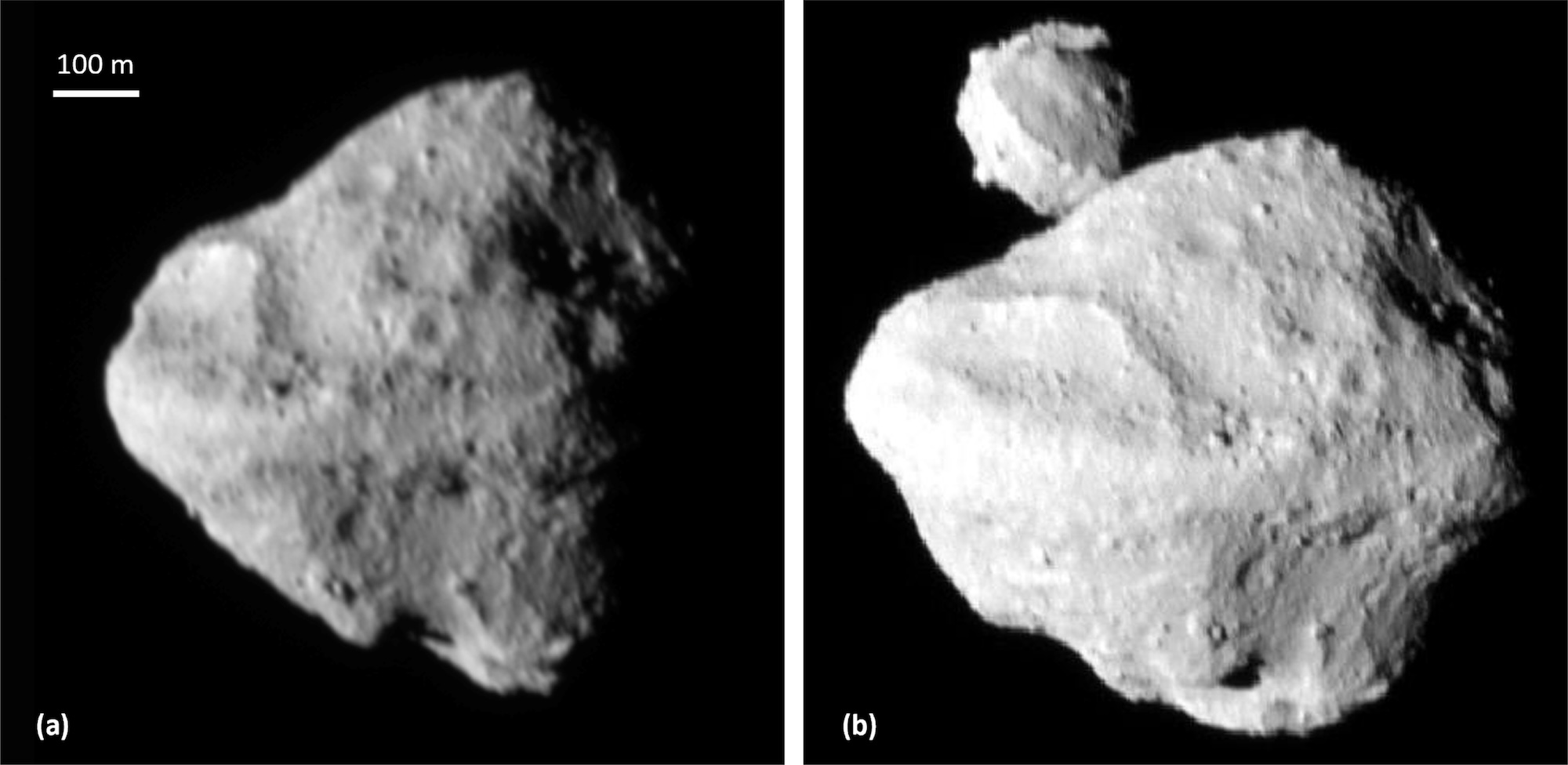
Two images of Dinkinesh from the Lucy mission. The second image features its satellite, Selam. [Bierhaus et al. 2025]

During this flyby, Lucy flew within 430 km (267 mi) of the asteroid and made a surprise discovery: Dinkinesh has a tiny companion, which has been named Selam. (The name Dinkinesh comes from the Amharic name for the Lucy fossil discovered in 1974; Selam is similarly named after a hominid fossil that is sometimes called “Lucy’s baby.”) Remarkably, Selam is the first known asteroid satellite that is a contact binary, made up of two separate bodies that have gently merged into one.

Craters and Boulders

In a recent research article, Edward Bierhaus (Lockheed Martin Space) and collaborators analyzed Lucy flyby images to study the surfaces of Dinkinesh and Selam. The team analyzed global features like troughs and ridges and measured visible craters and boulders.

craters on Dinkinesh and Selam

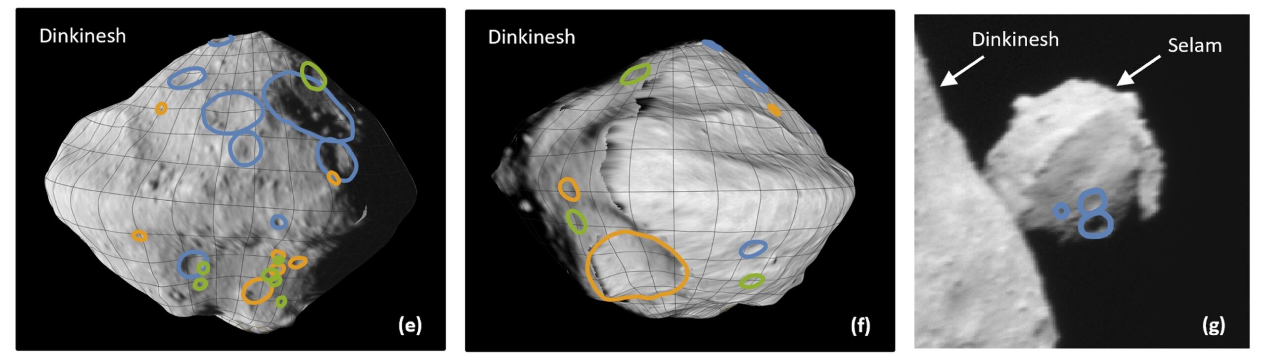
Locations of craters on Dinkinesh and Selam. The blue lines indicate the most confidently identified craters; orange and green lines mark craters identified less confidently. Click to enlarge. [Bierhaus et al. 2025]

While the small numbers of craters detected — 29 for Dinkinesh and 3 for Selam — makes further analysis difficult, the team determined that Dinkinesh’s crater size–frequency distribution is shallower than expected, though similar to that of small near-Earth asteroids (e.g., Ryugu). The seemingly shallow distribution may be an effect of the phase angle and resolution of the observations, or it could be a sign of impact armoring or other surface processes.

The size–frequency distribution of Dinkinesh’s boulders, on the other hand, is somewhat steeper. This discovery may mean that S-type (stony) asteroids like Dinkinesh have different boulder size distributions than C-type (carbonaceous) asteroids.

Possible Histories

An analysis of the collisional timescales in the main asteroid belt suggests that Dinkinesh is a fragment of a larger asteroid that was split apart at least once, though it’s not yet possible to say which parent body it might have come from. After splitting off from its parent asteroid, Dinkinesh appears to have been subjected to the Yarkovsky–O’Keefe–Radzievskii–Paddack (YORP) effect. This effect arises when sunlight falls on a small asymmetric asteroid, creating a torque that can alter its spin rate. In extreme cases, the YORP effect can crank up an asteroid’s spin rate so much that it sheds some of its surface material or flies apart altogether.

Sumak Fossa and Fab Dorsum on Dinkinesh

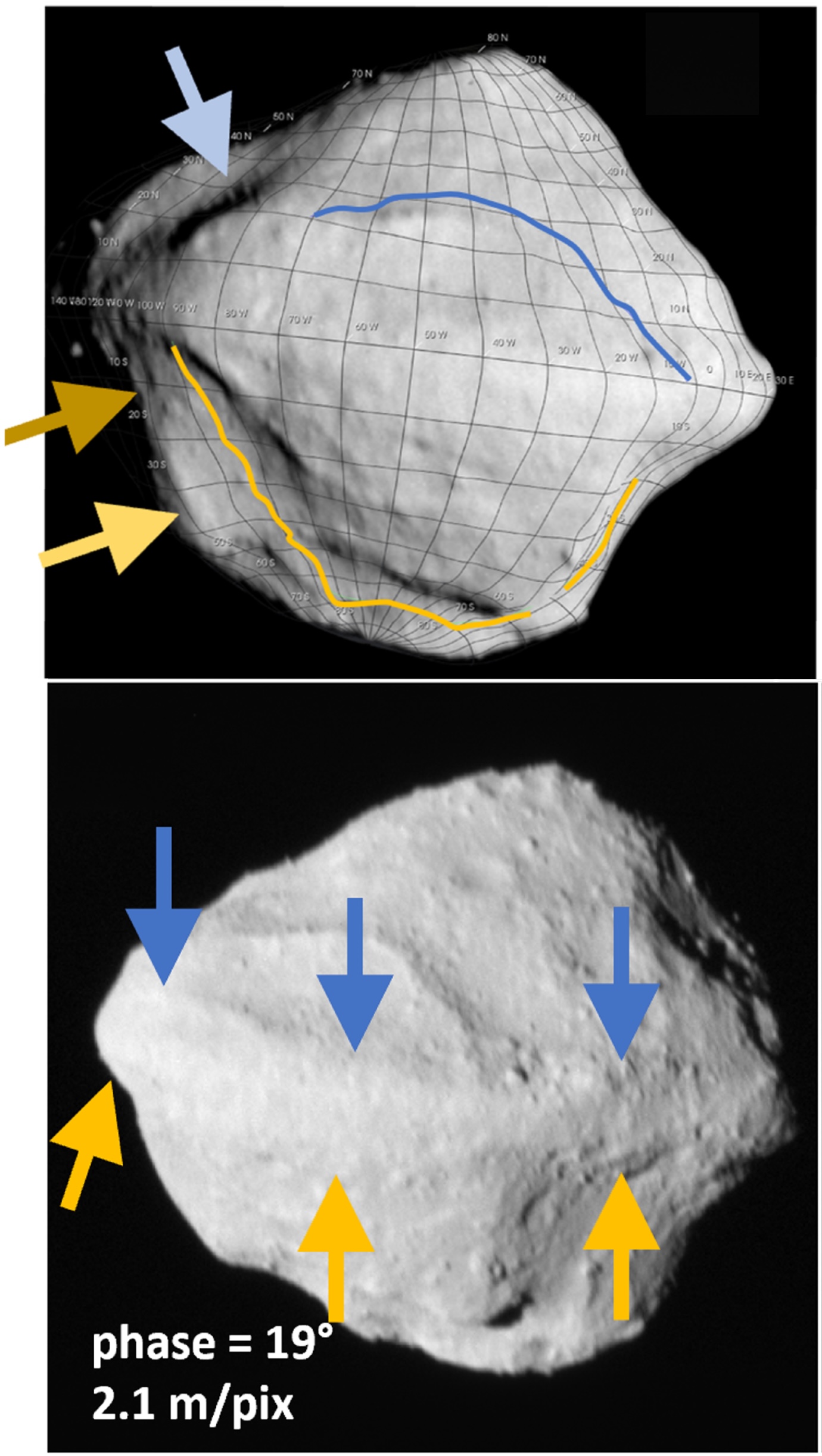
Locations of Sumak Fossa (top) and Fab Dorsum (bottom) indicated with arrows. [Adapted from Bierhaus et al. 2025]

Dinkinesh seems to show clear signs of YORP-driven structural failure. Sumak Fossa (a large trough) and Fab Dorsum (a ridge running along the asteroid’s equator) may have formed through this process. If Sumak Fossa was excavated by a YORP-induced mass-shedding event, both Fab Dorsum and Selam could have formed out of the cast-off material.

With Lucy en route to its primary objective, there’s still much for us to learn from this mission about the small bodies of our solar system. In the meantime, be sure to check out the full article linked below, as there are far more details about Dinkinesh and Selam than could be included in this short summary!

Citation

“The Geology of a Small Main-Belt S-Class Binary Asteroid System: Dinkinesh and Its Contact Binary Satellite Selam as Observed by the Lucy Mission,” E. B. Bierhaus et al 2025 Planet. Sci. J. 6 299. doi:10.3847/PSJ/ae1968

The post Details on Dinkinesh and Its Surprise Satellite from the Lucy Mission appeared first on AAS Nova.

  •  

Pulling Back the Curtain on DART Ejecta

In September 2022, the Double Asteroid Redirection Test (DART) mission served as the first attempt at redirecting a near-Earth asteroid — an experiment testing humanity’s ability to fend off any threatening Earth-bound asteroids. A recent study presents the first 3D reconstruction of the impact ejecta, suggesting that the blown-out material is more complex than previous models considered.

DART-ing into Dimorphos 

The DART spacecraft intentionally smashed into Dimorphos, the small and unassuming moon of the larger asteroid Didymos. This space-based crash test aimed to determine if kinetic impactors like DART could successfully change an asteroid’s course through the solar system. Dimorphos’s orbit was indeed shortened by roughly 30 minutes, confirming that ramming an asteroid with a spacecraft could be a viable method of planetary defense. However, determining exactly how much an asteroid’s path will be altered is not necessarily straightforward. When a spacecraft collides with an asteroid, the impactor imparts momentum to the target, and any material excavated from the impact site can also alter the asteroid’s course.

DART’s impact launched a significant spray of rubble, or what researchers call an ejecta curtain. The ejecta curtain is typically modeled as a cone, using a simple geometry to determine its contribution to momentum transfer. However, when looking closely at imaging taken soon after the collision, the real physical structure of the ejecta appears to be more complex. Untangling the true 3D distribution of the ejecta is necessary to understand how momentum was actually distributed among escaping ejecta, better estimate the total mass ejected from Dimorphos, and improve modeling of the Didymos system’s orbit after impact.

DART ejecta

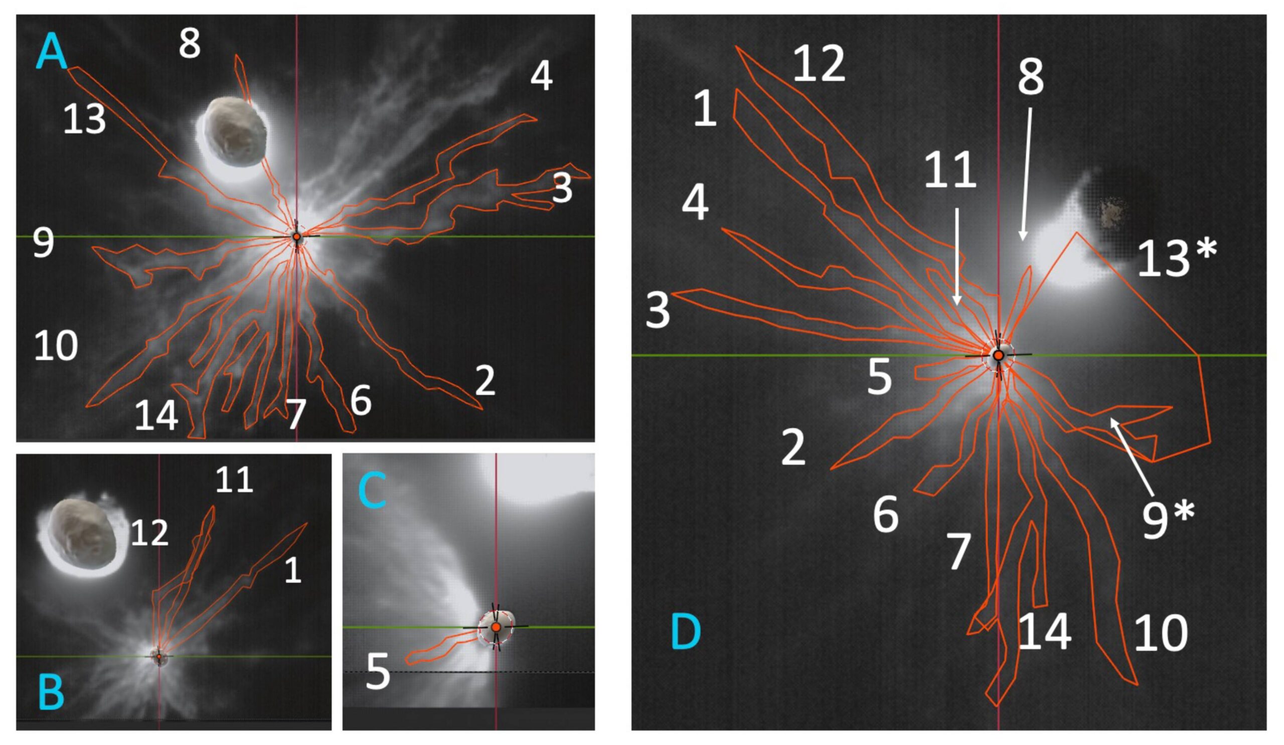
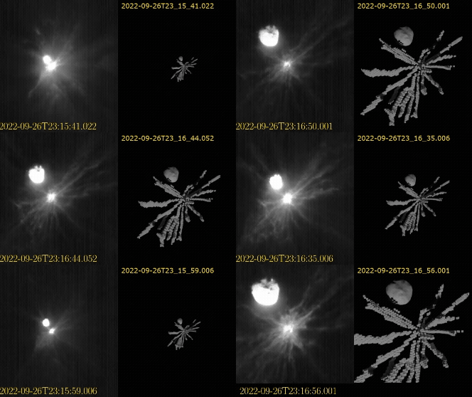
LICIACube images of the DART ejecta curtain with the 14 distinct features identified in this study outlined in red. Click to enlarge. [Deshapriya et al 2026]

Determining Debris Distribution

Seeking to better characterize the ejecta curtain, a team led by J. D. P. Deshapriya from Italy’s National Institute for Astrophysics used data from the Light Italian CubeSat for Imaging of Asteroids (LICIACube) that flew behind the DART spacecraft to capture images of the system shortly after the impact. After careful image handling to bring out diffuse and faint material, the researchers identified 14 distinct ejecta features across the flyby imaging. LICIACube viewed the aftermath both side on and face on, providing valuable 3D information about the distribution and motion of the ejecta. 

DART ejecta animation

Animation of the DART ejecta as the LICIACube spacecraft approached the impact. The left shows the images taken by the spacecraft, and the right shows the 3D model produced for the ejecta. Click to play animation. [Deshapriya et al 2026]

Using 3D modeling software, the researchers traced each of the 14 distinct features across the images and reconstructed a 3D representation of the ejecta morphology. While earlier models assumed symmetric cone-like geometries, this 3D modeling revealed clear asymmetric and non-uniform structures within the ejecta curtain. These variations point to underlying heterogeneities in the impact site on Dimorphos — surface and subsurface composition naturally link to the resulting ejecta distribution according to previous laboratory experiments. The spatial and directional features uncovered in this study highlight the limitations of models that attempt to characterize ejecta curtains with symmetric and uniform distributions. Refining these model parameters will better match observations and better predict momentum transfer in future missions. 

Planetary Defense

What does this mean for planetary defense? While simplified symmetric cone models provide helpful approximations for kinetic impactor missions, they do not fully capture the true complexity of the impact. This study shows that local variations in an asteroid’s surface and interior properties can directly influence the resulting ejecta distribution and motion. The true momentum imparted to the target asteroid depends heavily on the specific ejecta material, and these details inform how effective planetary defense missions can be in redirecting asteroids. Incorporating realistic, observation-driven ejecta distributions into modeling frameworks is essential to achieve reliable predictions for future planetary defense missions.

Citation

“3D Reconstruction of DART Ejecta at Dimorphos Reveals an Anisotropic, Filamentary Structure,” J. D. P Deshapriya et al 2026 Planet. Sci. J. 7 4. doi:10.3847/PSJ/ae2c64

The post Pulling Back the Curtain on DART Ejecta appeared first on AAS Nova.

  •  

Sun Glitter and Sunglint on Titan’s Hydrocarbon Seas

Titan sunglint

Earthlike yet alien, Titan is the only solar system body other than Earth known to host persistent liquid on its surface. The glint of sunlight on this surface liquid provides a means to study the complex interplay between Titan’s seas, shorelines, and atmosphere.

When the Sun Hits the Sea as Seen by Cassini, That’s a Mare

specular reflection on Titan

The first image of specular reflection of sunlight off Titan’s hydrocarbon seas, taken on 8 July 2009 by Cassini. [NASA/JPL/University of Arizona/DLR]

In 2009, the Saturn-orbiting Cassini spacecraft spotted the glare of sunlight reflecting off a sea of liquid on the surface of Titan, Saturn’s largest moon. This observation of specular (i.e., “mirror-like”) reflection, or sunglint, confirmed the presence of liquid on Titan’s surface — what researchers now know to be oily lakes and seas of liquid hydrocarbons like methane and ethane.

A recent research article from Michael Heslar and Jason Barnes (University of Idaho) yields new insight into the behavior of Titan’s seas and coastal regions in Punga Mare. Punga Mare, located nearly at the north pole, is the smallest of Titan’s named seas and holds the distinction of being the first place where extraterrestrial waves were definitively identified.

Summering at Punga Mare

In the Cassini observation selected for this study, it’s summertime in the northern hemisphere, with balmy temperatures hovering just above 90K (−298℉/−183℃). Cassini viewed Punga Mare from an altitude of roughly 6,000 kilometers and at an oblique angle of 126 degrees. From this angle, Titan’s landmasses appear dark and the sea appears bright.

diagram of the geometry of specular reflection and sun glitter

The geometry of specular reflection (sunglint) and sun glitter. The incidence and emission angles, i and e, are equal. Click to enlarge. [Heslar et al. 2020]

Several anomalously bright features, collectively called specular features, appear in and near Punga Mare. These features are examples of sunglint and sun glitter. Sunglint occurs when sunlight reflects off a smooth surface as light reflects off a mirror, with the angle of the incoming sunlight equal to the observer’s viewing angle. Sun glitter is a related phenomenon that occurs outside the sunglint zone, where localized changes in the angle of the surface — from waves, for example — reflect sunlight toward the observer.

Coasts, Islands, and Inlets

Punga Mare sunglint and sun glitter

Cassini Visual and Infrared Mapping Spectrometer observation of Punga Mare at wavelengths of 5.0 (red), 2.8 (green), and 2.0 (blue) μm. Click to enlarge. [Adapted from Heslar & Barnes 2025]

Heslar and Barnes identified specular features along the coastline, bordering a chain of islands, out at sea, and in coastal inlets.

The bright areas along the coast appear to overlap both the sea surface and the land surface. While it’s not yet clear exactly what causes this brilliant coastal outline, Heslar and Barnes speculated that it may be evidence for waves along the coastline; rough seas may also be the cause of the sun glitter illuminating the Hawaiki island chain and out at sea.

The specular features associated with inlets may mark where rivers flow into or out of Punga Mare. Rather than wave activity, these bright areas might mark where nitrogen has bubbled up to the surface.

Altogether, this study demonstrated the variety and depth of information that can be gleaned from a single sunglint observation — and the authors closed by noting how effective an orbiter would be for studying ocean behavior on Titan. NASA’s upcoming Dragonfly mission may also be able to capture sunglint as the spacecraft leapfrogs across Titan’s surface.

Citation

“Sea Surface and Hydrological Activity Observed in Titan’s Punga Mare,” Michael F. Heslar and Jason W. Barnes 2025 Planet. Sci. J. 6 74. doi:10.3847/PSJ/adbc9e

The post Sun Glitter and Sunglint on Titan’s Hydrocarbon Seas appeared first on AAS Nova.

  •  
❌